
Power Generation & Control
I added a sound decoder to a Farish class 57 locomotive this weekend. And it included a new feature I've not had on the railway before: a "keep alive" capacitor (a 470uF tantalum capacitor to provide some local energy storage if there is a poor track contact).
The inrush current into that capacitor could be substantial. After putting it on the track, we found that we'd get occasional "track shorts" reported by PM42 and worse at the fiddle yard end.
I used Loconet-Checker to change the current thresholds on all the PM42 up one notch (from 3A to 4.5A on two, and from 4.5A to 6A on the others, noting that I have two different build standards with different sets of thresholds). That seems to have solved the problem.
In the early days of DCC, power was fed from one source (the "booster") to the whole railway. That was simple, and allowed a lot of wiring to be removed.
Quite quickly however at least three problems were found with this arrangement:
- One booster may not be able to provide enough power for the whole railway;
- A track short in one area - for example caused by a derailed train - caused power to be removed everywhere;
- When there was a short, power was also taken away from accessory decoders, so points could not be changed.
DCC has always allowed several boosters to be used. Separate regions known as "Districts" are electrically isolated by gapping both rails; then a separate booster feeds each District. This allows the total power problem to be resolved: if the separate districts each have several moving trains, the railway as a whole can have more trains operating than if a single booster were used.
Using a separate booster to feed the accessory decoders also became a recognised thing to do. This allows power to the accessory decoders to be always there, even if there are track shorts. However this is an expensive solution; modern accessory decoders (e.g. DAC20, DS64) provide alternative solutions to solve this.
Even if several boosters are used, it is likely that a track power short will affect quite a large area simply because boosters are relatively expensive and likely to cover bid sections of railway. What was needed was the electronic equivalent of a "circuit breaker": enter the Power Manager.
Power Managers act as self resetting electronic fuses. If there is a short, they remove track power; when the short is removed, they re-connect the power. The difference between a power manager and a booster is that the power manager itself doesn't generate the DCC rail signal; you still need a booster for that. The critical advantage over a booster is that they are about a tenth of the price, so you can aspire to have more of them. The output of a power manager feeds a "zone".
The Digitrax PM42 is a quad power manager. Each section behaves independently; that provides up to 4 separate power feeds. Each feed will be isolated from the others, so a short in one section will not affect the others.
Each end of the railway is a separate booster district, fed by its own DB150 booster. This provides up to 10A track power; with an N gauge loco taking perhaps 0.25A, it is definitely overkill. The accessory decoders are fed by the DCS100 booster output, ensuring they always have power.
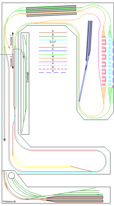
Each booster district is split into separate power zones. The principle I've used here is to separate the main lines from the station & yard areas: derailments are much more likely in those, and they need to be separated. The main lines, on the other hand, are unlikely to suffer because the train movements are more simple: consequently these don't need to be broken up as much.
The South Downs Railway has four reverse loop zones. One reverse loop - with three parallel storage tracks - is located under Portsmouth station. The other, with a single track, is in front of Petersfield station. These tracks each need their own autoreverser. Each reverse loop area - under Clanfield and by Petersfield - has its own PM42 channel for short circuit protection: I have used two because they are in separate booster districts.
Here is a list of the zones used on the railway:
| Booster | Board | Channel | Zone | Track Area |
Block Dets |
Detectors |
|---|---|---|---|---|---|---|
| DB150 1 | PM42 31 | 1 | A | Portsmouth Approach & platforms | 12 | 52 53 54 55 57 58 59 60 65 66 67 68 |
| DB150 1 | PM42 31 | 2 | B | Portsmouth Yard, Engine Shed & Eastleigh | 9 | 50 51 56 61 62 63 64 69 70 |
| DB150 1 | PM42 31 | 3 | C | Green line at Portsmouth end | 12 | 25 26 27 28 36 38 71 73 74 99 100 109 |
| DB150 1 | PM42 31 | 4 | D | Portsmouth Loop 3 reverse loop | 2 | 33 102 |
| DB150 1 | PM42 32 | 1 | E | Portsmouth Loop 1 reverse loop | 2 | 35 104 |
| DB150 1 | PM42 32 | 2 | F | Portsmouth Loop 2 reverse loop | 2 | 34 103 |
| DB150 1 | PM42 32 | 3 | G | Orange line at Portsmouth end | 14 | 23 24 29 30 31 32 37 39 72 75 76 101 105 110 |
| DB150 1 | PM42 32 | 4 | H | Reverse loops isolator | 0 | |
| DB150 2 | PM42 33 | 1 | J | Reverse loop isolator | 0 | |
| DB150 2 | PM42 33 | 2 | K | Clanfield | 8 | 17 18 19 20 21 81 82 83 |
| DB150 2 | PM42 33 | 3 | L | Green line | 16 | 12 14 15 22 42 43 44 45 49 77 80 94 95 96 106 107 |
| DB150 2 | PM42 33 | 4 | M | Orange line | 12 | 13 16 40 41 46 47 48 79 97 98 108 111 |
| DB150 2 | PM42 34 | 1 | N | Petersfield Loop | 2 | 11 88 |
| DB150 2 | PM42 34 | 2 | P | Fiddle yard green | 12 | 2 3 4 5 84 85 86 87 117 118 119 120 |
| DB150 2 | PM42 34 | 3 | R | Fiddle yard orange | 12 | 6 7 8 9 90 91 92 93 113 114 115 116 |
| DB150 2 | PM42 34 | 4 | S | Fiddle yard sidings | 4 | 1 10 89 112 |
Many railways include what are called "reverse loops". These are track constructs that allow a train to urn around and come back the way it arrived. These are fine operationally, but need some care when providing the power to them.
The problem with a reverse loop is obvious if you draw out the two rails: they end up shorting out. With a DCC powered railway, the standard solution was to stop the train in the reverse loop, then reverse the power and drive it out with reversed polarity. DCC provides an alternative: the "autoreverser".
An autoreverser is simple: it feeds power to a track section, with an ability to reverse polarity to that section. The reverse loop is powered in three parts: each end is fed according to the track leading to it, while the centre section is fed by an autoreverser. When the train either drives into or out of the centre section, a short occurs when the wheels first cross the gap. The autoreverser detects the short and quickly swaps over the polarity (typically with a relay). That releases the short, allowing the train to continue.
For this to work, the centre section needs to be larger than the longest train that has its wheels connected through.
Digitrax provide an AR1 autoreverser, which is comparable to several other products. Its PM42 quad power manager can also have its outputs individually programmed to be autoreversing. Some claim the PM42 has problems when being used for autoreversing but I have seen no evidence of that with several reverse loops on my railway.
One thing to remember is that an autoreverser is not a power manager. If a short occurs in the reverse loop, the autoreverse will keep changing polarity to try to clear it but will not succeed. It is possible to use a power manager then an autoreverser to provide both functions; that would use two of the 4 zones on a PM42.
These are the settings used for PM42 modules on the railway:
| Board | Ch | Zone | Trip current | Configuration | Speed | Option Switches |
| PM42 31 | 1 | A | 3A | Short circuit Manager | normal | sw6=t; sw3=t; sw5=t; |
| PM42 31 | 2 | B | 3A | Short circuit Manager | normal | sw14=t; sw11=t; sw13=t; |
| PM42 31 | 3 | C | 3A | Short circuit Manager | normal | sw22=t; sw19=t; sw21=t; |
| PM42 31 | 4 | D | 3A | Auto Reverse | fastest | sw30=c; sw27=c; sw29=t; |
| PM42 32 | 1 | E | 3A | Auto Reverse | fastest | sw6=c; sw3=c; sw5=t; |
| PM42 32 | 2 | F | 3A | Auto Reverse | fastest | sw14=c;sw11=c; sw13=t; |
| PM42 32 | 3 | G | 3A | Short circuit Manager | normal | sw22=t; sw19=t; sw21=t; |
| PM42 32 | 4 | H | 3A | Short circuit Manager | normal | sw30=t; sw27=t; sw29=t; |
| PM42 33 | 1 | J | 4.5A | Short circuit Manager | normal | sw6=t; sw3=t; sw5=t; |
| PM42 33 | 2 | K | 4.5A | Short circuit Manager | normal | sw14=t;sw11=t; sw13=t; |
| PM42 33 | 3 | L | 4.5A | Short circuit Manager | normal | sw22=t; sw19=t; sw21=t; |
| PM42 33 | 4 | M | 4.5A | Short circuit Manager | normal | sw30=t; sw27=t; sw29=t; |
| PM42 34 | 1 | N | 4.5A | Auto Reverse | fastest | sw6=c; sw3=c; sw5=t; |
| PM42 34 | 2 | P | 4.5A | Short circuit Manager | normal | sw14=t; sw11=t; sw13=t; |
| PM42 34 | 3 | R | 4.5A | Short circuit Manager | normal | sw22=t; sw19=t; sw21=t; |
| PM42 34 | 4 | S | 4.5A | Short circuit Manager | normal | sw30=t; sw27=t; sw29=t; |
All power zones were intended to have 3A trip current. Some zones have had to have the settings adjusted because when we measured the current, two board were more sensitive and tripped incorrectly at lower currents (not far from half of the intended current value).