
Power Generation & Control
All the PM42 zones were programmed to trip at 3A current load. So why were some zones tripping when any train ran, while others did not?
That kind of problem demanded a scientific investigation. What I did was to purchase a set of 47Ω power resistors (rated at I think 3W each). Each of these added across the rails would add a 0.25A load, approximately; with some accurate voltage measurements and a spreadsheet I would know the truth. As it turns out, my multimeter when set to "AC Volts" gave a near exact voltage reading: I calibrated it against true peak-peak rail voltage using an oscilloscope.
The results, when I got them, were surprising: two of my PM42 modules had current trips close to the "brochure" figures; the other two - at the fiddle yard end- had trip points significantly lower than the others. I'd bought them at different times; I don't know if there has been a design change. However armed with these measurements I was able to balance the current limits by reprogramming the over-sensitive PM42 modules.
How much current is being drawn from the DCC booster? It isn't obvious, until its current limit trips. It isn't easy to measure, because it is an AC current. But there is a product that measures it, called the Ramp Meter.
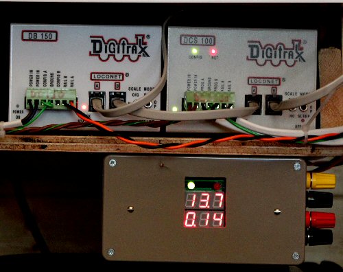
The ramp meter sits in the power feed from the booster to the railway. It reports two things: the rail voltage (13.7v here); and the current drawn (0.14A here).
On my railway, it tells me what I'd suspected: that the current drawn is tiny. Typically I see half an amp max with two trains running at that end of the railway. When the picture was taken there was nothing running: 0.14A is the current "lost" in resistor wheelsets and static load of the DCC decoders.