
Point Control
DCC accessories are used for several purposes: to change points; to control signals; to turn on or off scenery accessories; and for special functions. This page describes the range of numbers used.
| 1-99 | Points |
| 201-399 | Signals |
| 401-500 | Turntable (401: normal DCC address; 451: Marklin address) |
| 501-700 | Scenery |
| 901-999 | special functions |
| 901 | DTM30 interlock for Eastleigh depot |
| 911 | DTM30 interlock for Portsmouth station |
| 912 | DTM30 interlock forPortsmouth Approach |
| 913 | DTM30 interlock for Portsmouth container depot and engine shed |
| 921 | DTM30 interlock for Clanfield |
| 922 | Activated when crossing barriers are down to allow signals to go green |
The DAC20 accessory decoders all have very similar settings.
They are powered from a DC 24v supply, rather than from track power. This means they would get commands even if there were a DCC short. (It also means they can't participate in DCS100 command station routes, but I don't use those). So the 24v power is connected to SK1 pins 1&2; and the boards have a ground wire connected to the command station ground. The "use LocoNet commands" option is ticked in locoanalyse.
For SEEP point motors, the default output timing is used. That means each output is active for 0.5s, and there is a 0.8s delay between outputs programmed for the capacitor discharge unit. That means if several points are changed at the same time, the DAC20 will space them apart to make sure the CDU recharges.
There is an option in Traincontroller to put a delay on each junction when points are changed, before it will drive a trian through. I think that is set at 1 second, which seems to be long enough to allow 2-3 points to be changed.
So far I've tried several types of point motor on the railway:
The majority are the "Seep" PM-1 type: a solenoid point motor on a PCB with a built in switch. Generally these have worked OK but I have had a few issues. One motor just fell apart, and had to be replaced. Soldering the wires to the PCB has been a problem: I don't like permanently wired connections and tried to put "push on" terminals onto the PCB. Unfortunately that's too brutal for the PCB tracks. The next version was to drill holes and have the PCB laminate help out with the mechanical integrity, which has been better. In future I will probably use trailing wires and crimp "bullet" connectors on the wires. I've also had a problem with the PCB switches sometimes not making contact. This has been cleared with a squirt of switch cleaner. It could have been caused by flux from the soldering process.
In the Clanfield area I used Tortoise motors. These are well known and very reliable. They have a two pole switch which can switch frog power. There's a lot of misinformation about the rating of the switch contacts. They won't reliably break a 5A current: but that would only happen if you change the point while a 5A fault is flowing through it. If your booster shuts down when there's a track short (use a coin test) then this isn't an issue. They are quite bulky.
I have a couple of places that are quite restricted. In one of these I had a Peco solenoid motor with a long pin up through the baseboard, and a micro-switch on the motor body. This arrangement I've found to be unreliable: sometimes it will just stick. I've given up and removed them. I think if you didn't have the switch, or didn't have a long pin extending through 15mm of baseboard and cork, it would be fine. It's the combination of the two that causes the problem.
In one of those restricted places I've used a "Cobalt" motor. These are similar in idea to a Tortoise, but smaller. The DAC20 drives it fine. One difference is you can't move the output by pushing it across by hand.
I've purchased, but not yet tried, a batch of "Conrad" motors. These are powered constantly but have a limit switch. The DAC20 needs an output adapter to drive them.
In some places I've chosen to use "Tortoise" point motors. These are quite different from solenoid ones: they are constantly powered, and operate by running a motor one way or the other until it stalls. The motor drives a moving arm, from which a spring wire operates the point itself. The motor includes two SPDT switches for frog power etc. I have followed advice elsewhere and used stiffer wire: I used 0.8mm piano wire.
The Tortoise is a "slow motion" motor: it will move the point blades across slowly, as would happen on a "real" railway. For that to happen, the over-centre spring on the Peco points needs to be removed. With Peco N gauge points (mine are code 55) this is particularly important because the tiebar is quite stiff to move. It is far easier to remove the spring before mounting the points - but as I discovered not impossible afterwards!
The DAC20 accessory decoders drive the Tortoise motor directly. Two wires from the output connector go to the motor - ignore the third central terminal. The same DAC20 also drives Seep motors - each output is individually programmed. Best of all the programming was done through a PC & LocoNet - reprogramming 5 outputs to Tortoise type took maybe 2 minutes. Finally the output jumpers on the DAC20 need to be swapped over to the "constantly powered" position.
I use 2.8x0.8mm "tab" connectors for the point motor connections. A simple solder tab is added to the motor, and crimp connectors are used on the wires. The result is a simple but reliable process with all joints connectorised for testing etc.
Once the point has been installed, the motor needs to be added underneath. There is a template marked for this on the instruction leaflet; cut it out and laminate it, and puncture the holes to be able to mark through with a pen. To get the position right, I put the tortoise upside down with its wire through the tiebar (photo).
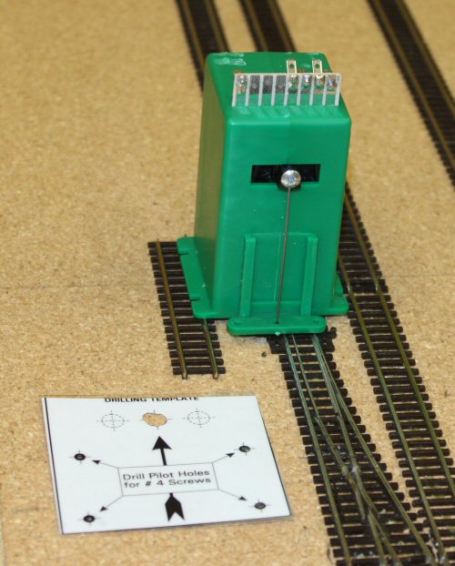
Finally offer up the template from underneath, and mark the 4 mounting holes. Remove the template and spot drill the 4 holes. The motor can then simply be screwed on; the excess actuating rod can be cut afterwards with strong, sharp cutters.
All of the points on the railway are DCC operated. This is vital for computer control: the computer needs to be able to set the track to the necessary position for any train movement.
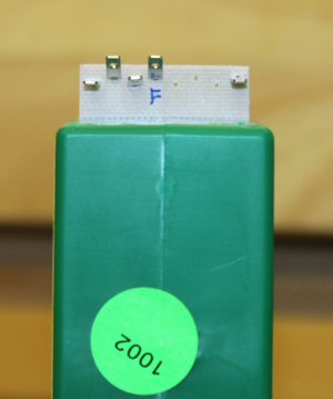
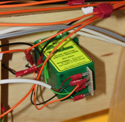
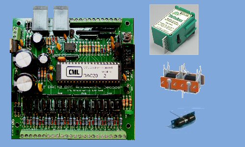
I've used CML Electronics DAC20 accessory decoders. The DAC20 controls up to 8 point motors of most types. The common "Peco" and "Seep" solenoid motors work well with the DAC20, and I've used those extensively. Both need a capacitor discharge power unit, and that is included on the DAC20 board. The DAC20 boards all have an auxiliary 24v supply.
On this railway, all that is needed now is a simple accessory decoder function. The DAC20 can also do automatic control of semaphore signals, and control lighting circuits; these may be added to the railway later.
The DAC20 has a LocoNet interface: this means that it can report the point state to LocoNet after power up. This way, all other devices - e.g. signal controllers - will "know" the state of all of the points automatically.
We have used several different kinds of point motor:
- The early points were all controlled by Seep point motors. These are fairly low cost, and have an integral switch. I have had a couple fail (one disintegrated, an done had a rough edge to the switch contact on its PCB which "snagged" occasionally). Also I've had the switch contact become unreliable, but this has always been resolved with a squirt of switch cleaner. I'm wondering if flux ran on to the PCB while soldering wores and connector pins.
- Clanfield station uses Tortoise type point motors. There are fairly expensive, but absolutely reliable. "You get what you pay for" some say.... they are als very bulky, and on the track sections with trains running underneath there's no way they would fit.
- One point is mounted very close to the timber frame, and we tried a Peco point motor plus microswitch. This has proved unreliable: my experience with these is that eventually they stop sliding across because of mechanical friction. WD40 may resolve it..... but I've replaced it with a "Cobalt" motor from DCC Concepts. This is like a Tortoise, but smaller.
- I have purchased a number of "Conrad" motors for areas where train run underneath. Not tried them yet. The DAC20 will need an output adapter for those.