
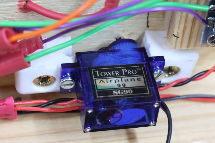
The first animated scenery item for Eastleigh is the yard access gate: this should open to allow trains in and out, but be closed otherwise. The plausible location for the gate isn't ideal: its edge will necessarily be very close to the edge of the lifting section. But the means of control is clear: a servo with a vertical shaft.
The servo itself was simple. Plastic blocks (B&Q furniture corner blocks, modified) were used to mount the servo under the lifting baseboard section. A metal shaft was inserted into the hole on the servo spindle - normally that hole takes a screw to secure the cam. the shaft of a flat-bladed jewellers' screwdriver turned out to be a perfect fit. With a vertical hole drilled from above, we were able to mount the servo with its spindle vertical and not binding on the edges of the hole.
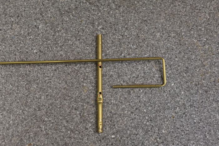
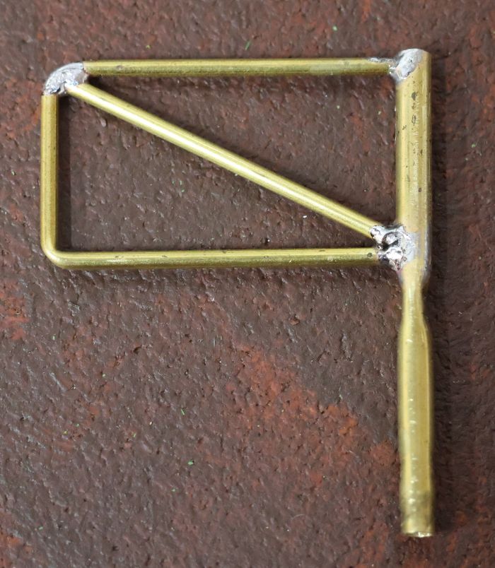
The gate was made from brass tube: approx 1.5mm and 3mm diameters. An upright tube was crimped, so that it fits around the end of the screwdriver; that meant it would be turned by the servo but could be lifted off. Then the smaller tube was measured and bent into a deep "U" shape. We were able to drill the larger tube so the smaller tube would fit into it; the joints were then soldered. A brass cross-piece completed the frame of the gate.
I have some nylon mesh that makes a passable chainlink fence to be added over the top.
The next challenge was controlling the gate. An MSC8 Scenery Animator was the obvious choice; I will need other outputs from it for other things in the yard. Output 2 was programmed to be a servo output (CV10=4; CV54=70; CV55=210; CV56&57=0; CV58=0; CV59=10; CV60=64).
Finally Traincontroller has been programmed to operate the gate as part of the routes into the yard. A switch needs to be added to a switchboard, then it can be operated by the route being activated and deactivated.
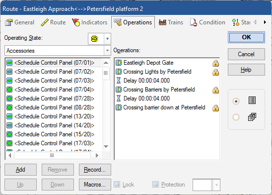
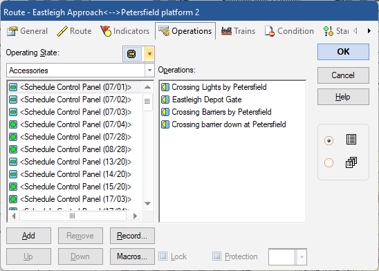
And from the point of view of an operating gate, that's it. Scenic detail is all that needs to be added.
This was fairly simple: an MSC8 scenery animator to control effects in and around the engine shed at Portsmouth. The unit itself is mounted under the Portsmouth baseboard, and powered by accessory DCC track power. Its outputs are as follows:
| Output | DCC | Function | CVs |
| 1 | 573 | ||
| 2 | 574 | servo: engine shed door | CV10=4; CV54=220; CV55=60 |
| 3 | 575 | servo: yard gate | |
| 4 | 576 | on/off lighting in engine shed | CV12=2 |
| 5 | 577 | welding in shed | CV13=0; CV21=1 |
| 6 | 578 | ||
| 7 | 579 | ||
| 8 | 580 |
Out turntable is a Fleischmann 9152 powered by a CML Electronics TXC1. During a recent operating session, we found the DCS100 command station beeping 24 times when it powered up; thereafter LocoNet devices including throttles didn't work. 24 beeps isn't a recognised code - what was happening?
I measured the LocoNet voltage from pin 2 to pin 3 on a LocoNet cable - around 8V. That's far too low - with no throttles attached it should sit at around 13v. The LocoNet is sectioned, so we were able quickly to isolate the problem to the Portsmouth area, then by elimination to the TXC1.
The TXC1 has an 18 ohm resistor between its power ground and LocoNet ground: that resistor was discoloured through overheating. Experience says that is a power supply problem (for example if the board power feed is biased relative to mains ground). It was a new power supply, but that wasn't the case. It turns out the 3 red/yellow/grey wires from the turntable were biased to half track voltage.
After taking off the turntable bridge and disassembling the mechanism, a possible cause was clear: there is a phosphor bronze springy strip running under each rail, and therefore under the body of the motor. The way the strip was mounted, it was springing up slightly (how far would be temperature dependent) and it could have made contact with the body of the motor. I've now attached a very think strip of plastic card to the springy strip and glued it down, so that it should remain isolated from the motor. I also took the opportunity to bypass the relay that isolates one track end on the bridge, so the full length of the bridge is now permanently powered.
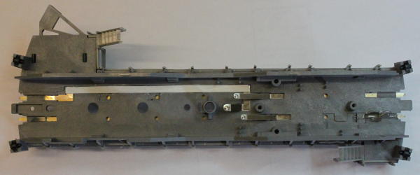
And... two days later the problem came back. I was able to remove the turntable bridge from the turntable (so it looks like the picture above) and still measure 0 ohms from a rail connection to the motor feeds: so there was conclusive proof that the turntable, not the controller, was at fault; and the problem wasn't in the slip rings. But it was the other rail that was shorted (the bottom rail as protographed above), with no obvious way for that to happen. In the end I removed the relay that isolates part of the track at the bridge ends, and all has been fine ever since. I've soldered the rail gap, so the bridge track is now powered along its full length.
This is a definitive list of all controlled scenery items on the South Downs Railway. (Note bold numbers are the ones to activate manually; the others operate automatically from that)
|
MSC8
|
DCC
|
Item
|
Comment
|
|
1
|
501
|
Clanfield windmill motor
|
50Hz motor.
|
|
1
|
502
|
Windmill light: yellow LED
|
flickering lamp effect
|
|
1
|
503
|
Clanfield church lighting
|
PWM lighting output
|
|
1
|
504
|
Clanfield station building lighting
|
PWM lighting output
|
|
1
|
505
|
Reserved for Clanfield station platform lights
|
PWM lighting output
|
|
1
|
506-508
|
unused | |
|
2
|
509-516
|
Petersfield area
|
PWM lights; mix of "often on" and "less often on" sequences.
CV9=6 (DC motor); CV10-16=1 (fast PWM)
CV17-24=2 (house light 1) (could be set to 3 for any driving upstairs lights, to be on less often)
CV32, 35, 38, 41, 44, 47, 50, 53 are random values in range 0-255
DCC gate CVs (34, 37, 40, 43, 46, 49, 52) all set to 1 so o/p 1 turns on or off all lights
|
|
3
|
517-524
|
Petersfield area
|
PWM lights; mix of "often on" and "less often on" sequences.
CV9=6 (DC motor); CV10-16=1 (fast PWM)
CV17-24=2 (house light 1) (could be set to 3 for any driving upstairs lights, to be on less often)
CV32, 35, 38, 41, 44, 47, 50, 53 are random values in range 0-255
DCC gate CVs (34, 37, 40, 43, 46, 49, 52) all set to 1 so o/p 1 turns on or off all lights
|
|
4
|
525
|
factory smoke generator
|
on 1 minute every 5 minutes
CV9=7; CV7=127; CV17=7
|
|
4
|
526
|
reserved for ladder raising servo
on when o/p 1 sequence active
|
CV10=4; CV33=1
|
|
4
|
527
|
fire engine lights
on when o/p 1 sequence active
|
on when smoke generator on; flashing light sequence
CV11=0; CV19=4; CV36=1
|
|
4
|
528
|
always on downstairs light (&3 other factory buildings)
|
PWM light
CV12=2; CV20=0
|
|
4
|
529
|
fire light 1
on when o/p 1 sequence active
|
no PWM; flickering light; on when smoke generator on
CV13=1; CV21=6; CV42=1
|
|
4
|
530
|
fire light 2
on when o/p 1 sequence active
|
no PWM; flickering light; on when smoke generator on
CV14=1; CV22=6; CV47=20; CV45=1
|
|
4
|
531
|
fire station flashing lights,
turned on when o/p 8 sequence is active
|
CV15=0; CV23=4; CV48=128
|
|
4
|
532
|
sequence for flashing light in fire station
|
on infrequently (house light 2 sequence)
CV16=0; CV24=3
|
|
5
|
533
|
Level crossing flashing light by Petersfield station.
|
CV9=9; CV6=64 (sets blink rate)
|
|
5
|
534
|
servo for barrier 1 (rear)
|
CV10=4
CV58=0 (no bounce); CV60=5 (tiny off delay)
|
|
5
|
535
|
servo for barrier 2 (front)
enabled when DCC command for output 2 is active
|
CV11=4
CV37=2
CV65=0 (no bounce); CV62=190 (barrier down position); CV67=5 (tiny off delay)
|
|
5
|
536
|
||
|
5
|
537
|
||
|
5
|
538
|
||
|
5
|
539
|
||
|
5
|
540
|
||
|
6
|
541-4
|
shop lights in Clanfield area
|
PWM lights; mix of "often on" and "less often on" sequences.
CV9=6 (DC motor); CV10-16=1 (fast PWM)
CV17,19,21,23=2 (house light 1); CV18,20,22,24=3 (house light 2, for upstairs lights)
CV32, 35, 38, 41, 44, 47, 50, 53 are random values in range 0-255
DCC gate CVs (34, 37, 40, 43, 46, 49, 52) all set to 1 so o/p 1 turns on or off all lights
|
|
6
|
545-8
|
Unused.
|
|
|
7
|
549-556
|
shop & house lights in Clanfield area
|
PWM lights; mix of "often on" and "less often on" sequences.
CV9=6 (DC motor); CV10-16=1 (fast PWM)
CV17,19,21,23=2 (house light 1); CV18,20,22,24=3 (house light 2, for upstairs lights)
CV32, 35, 38, 41, 44, 47, 50, 53 are random values in range 0-255
DCC gate CVs (34, 37, 40, 43, 46, 49, 52) all set to 1 so o/p 1 turns on or off all lights
|
|
8
|
557-564
|
house lights in Clanfield area
|
PWM lights; mix of "often on" and "less often on" sequences.
CV9=6 (DC motor); CV10-16=1 (fast PWM)
CV17,19,21,23=2 (house light 1); CV18,20,22,24=3 (house light 2, for upstairs lights)
CV32, 35, 38, 41, 44, 47, 50, 53 are random values in range 0-255
DCC gate CVs (34, 37, 40, 43, 46, 49, 52) all set to 1 so o/p 1 turns on or off all lights
|
|
9
|
565-572
|
Petersfield area
|
PWM lights; mix of "often on" and "less often on" sequences.
CV9=6 (DC motor); CV10-16=1 (fast PWM)
CV17=0, CV18=0 (station & signal box - on or off)
CV19=6 (cinema flickering light)
CV20-24=2 (house light 1)
CV32, 35, 38, 41, 44, 47, 50, 53 are random values in range 0-255
DCC gate CVs (34, 37, 40, 43, 46, 49, 52) all set to 1 so o/p 1 turns on or off all lights
|
|
10
|
573
|
Portsmouth engine shed: not used
|
|
|
10
|
574
|
Portsmouth engine shed door servo (Thrown=open)
|
|
|
10
|
575
|
reserved for a yard gate servo
|
|
|
10
|
576
|
lighting in engine shed
|
|
|
10
|
577
|
welding in engine shed
|
|
|
10
|
578-580
|
not used
|
|
|
11
|
581
|
not used (reserved for oil pump)
|
|
|
11
|
582
|
Eastleigh yard access gate
|
C=gate closed; T= gate open CV10=4; CV54=70; CV55=210; CV67, 57=40; CV58=0; CV59=1; CV60=64 |
|
11
|
583-588
|
not used
|
Effects are always THROWN for ON; CLOSED for OFF.
MSC8 number 4 has several outputs controlled by one operation. The smoke generator is operated by a sequence; it is on for approx 1 minute every 5 minutes. When the smoke generator output is active (i.e. for that 1 minute when the building is on fire) outputs 2, 3, 5 & 6 are activated. These then have their own sequences: to flash the fire engine lights, and to flicker LEDs to look like the fire itself.
MSC8 number 4 Output 7 has 2 sequences: a sequence that flashed the lights like a fire engine; and that whole output is turned on or off by output 8, which is on infrequently. This will give the appearance that a fire engine inside the fire station has its lights tested periodically.
MSC8 Board Locations:
| Board | Location | DCC | Power bus? |
| 1 | dropdown under Clanfield | 501 | Y |
| 2 | fiddle yard | 509 | Y |
| 3 | fiddle yard | 517 | Y |
| 4 | Under factory | 525 | Y |
| 5 | under crossing | 533 | Y |
| 6 | fiddle yard | 541 | Y |
| 7 | fiddle yard | 549 | Y |
| 8 | fiddle yard | 557 | Y |
| 9 | fiddle yard | 565 | Y |
| 10 | under Portsmouth | 573 | Y |
There are two power buses for MSC8 boards. One feeds Portsmouth and Eastleigh; the other feeds Clanfield, Petersfield and the vicinity of the fiddle yard. The DC power comes from those buses. This is because the Accessory DCC bus was overloading on inrush current into the reservoir capacitors on those boards.