Some of the train operations at the stations require a manual "join" or "separate" train set operation. The obvious way to initiate that is with a control panel pushbutton.
The way to do it is as follows:
- Add a pushbutton to the DTM30 that generates a LocoNet sensor message.
- In Traincontroller, add a contact indicator to a switchboard attached to that sensor.
- Add an accessory pushbutton to the switchboard.
- Set the operations of the contact indicator when lit to activate the pushbutton, and when not lit to deactivate the pushbutton.
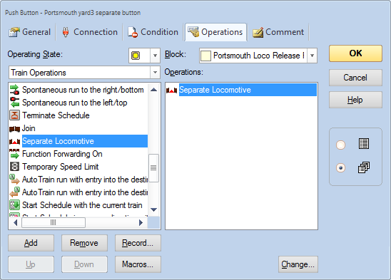
- Edit the accessory pushbutton. At the top of the "operations" tab is a place to associate the pushbutton to a block; choose the right block.
- Add an operation to the pushbutton when activated to execute a train operation "join locomotive" or "separate locomotive".
The DTM30 interlocks at Eastleigh used a spacial block in the approach road. We couldn't use the same approach at Clanfield, so we've tried the same approach as described in the DTM30 manual. That activates a route, preventing traincontroller activating others.
You need 3 elements on a switchboard to do this:
- A contact indicator that's activated by the DTM30 requesting the interlock. It's a general sensor whose number comes from the DTM30 front page.
- A point, that's set to THROWN when Traincontroller activates the interlock. The number is the same as programmed into the DTM30 interlock cell.
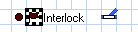
- A flagman, where all the logic is programmed.
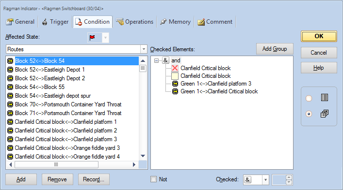
The flagman's trigger is the contact indicator. When the contact indicator lights, the flagman will try to activate.
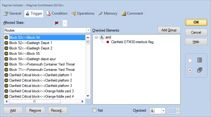
There is then a condition. The purpose of the condition is to say "don't let the the flagman activate if traincontroller is planning a train movement to or from Clanfield". We've used a block not reserved or occupied, and two routes not occupied:
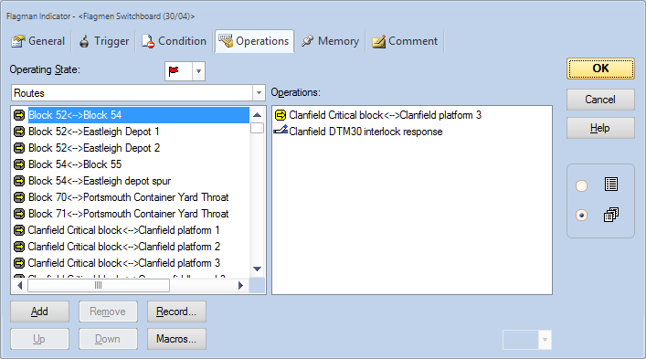
Finally the operations make the flagman do something. When the flagman activates, we need to set the special point to THROWN to tell the control panel it has control. We also need to do something that prevents Traincontroller being able to drive trains in or out of the station. We've chosen to activate a route from the Clanfield critical block in the approach to platform 3. Effectively that blocks the tracks.
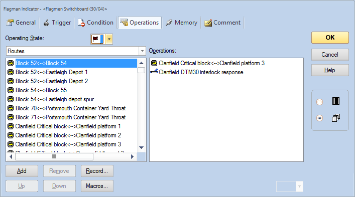
Finally when the flagman deactivates (ie when the contact indicator goes off in response to the DTM30 operator giving control back to the computer) we need to revers the last two steps - deactivating the route and setting the interlock point to CLOSED.
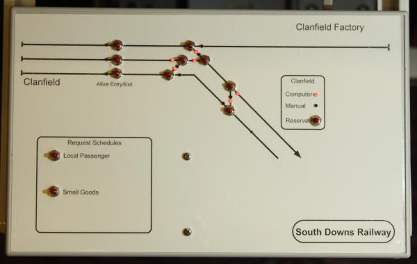
The last of the layout control panels (there's still a display panel to go...). This one controls Clanfield station. Nothing complicated - 6 points, a Traincontroller interlock and a few sensors to signal to Traincontroller.
DTM30 no. 455. Programming:
| Cell | Function | LED A | LED B | Pushbutton A | Pushbutton B |
| 1 | Point 19 | 19T | 19C | Toggle point | |
| 2 | Point 20 | 20T | 20C | Toggle point | |
| 3 | Point 23 | 23T | 23C | Toggle point | |
| 4 | Point 24 | 24T | 24C | Toggle point | |
| 5 | Point 21 | 21T | 21C | Toggle point | |
| 6 | Point 22 | 22T | 22C | Toggle point | |
| 7 | Sensor 165,5 | green LED | green LED | sensor on, latching | sensor on, latching |
| 8 | Sensor 165,7 | green LED | sensor on, latching | ||
| 9 | Interlock A, 921 | PC control (red) | manual control (green) | change interlock | |
| 10 | Sensor 165,8 | n/a | n/a | sensor on when pressed | sensor on when pressed |
Set to use sensor board 165 1-4 for interlocks
This is an unusual use for a DTM30. I wanted a panel that showed the different power zones and indicated when there was a track short. Otherwise, when you hear a PM42 relay click you have to go to the PM42 board itself, see which LED is lit then look up in a table which part of the railway that corresponds to. (If traincontroller is running, there are indicators and it does generate a spoken message, but that isn't always running particularly during development).
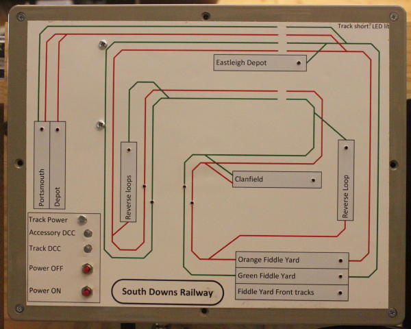
The general ideal is that the LEDs for each power zone are off until there is a short. Any red LED lit indicates a problem. I've included pushbuttons for "track power on" and "track power off". I've also included LEDs lit by the rail signal itself, so the track status is immediately clear.
DTM30 cell usage:
| Cell | Function | LED A | LED B | Pushbutton A | Pushbutton B |
| 1 | PM42 31 channel 1 | Portsmouth zone | track power off | track power on | |
| 2 | PM42 31 channel 2 | Portsmouth yard | |||
| 3 | PM42 32 channel 3 | Orange line | |||
| 4 | PM42 31 channel 3 | Green line | |||
| 5 |
PM42 32 channel 4 |
Reverse loop at Portsmouth | |||
| 6 | not used | ||||
| 7 | PM42 33 channel 3 | Green line | |||
| 8 | PM42 33 channel 4 | Orange line | |||
| 9 |
copy cell, copies cell 2 |
Eastleigh zone | |||
| 10 | not used | ||||
| 11 | PM42 33 channel 2 | Clanfield Zone | |||
| 12 | PM42 33 channel 1 | Reverse loop at Petersfield | |||
| 13 | PM42 34 channel 3 | Orange fiddle yard | |||
| 14 | PM42 34 channel 2 | Green fiddle yard | |||
| 15 | PM42 34 channel 4 | Front tracks in fiddle yard |
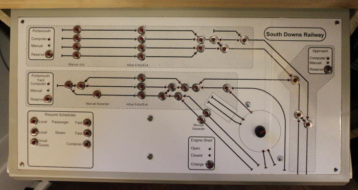
Portsmouth has a terminus station, a container depot and an engine shed all of which need manual operations as well as automated train operations. Traincontroller will deliver trains to and from the platforms, and take them away; but if the engine needs to be swapped, that's a manual operation. The DTM30 was designed for purposes such as this.
The control panel (just) fits inot a single DTM30; all of its cells are used. We've also integrated the rotary controller for the TXC1 turntable controller into the panel, forming a single point of control for the whole area. DTM30 cells are used for four purposes:
- To control points and display their current positions.
- To interlock with Traincontroller, so that track is used for manually controlled operations OR computer controlled ones but not both. There are 3 separate interlock zones of track - the station, the yard & engine shed, and the approach.
- To signal availability of the "roads" that Traincontroller can send trains to and from. This needs persistent (latching) sensor messages.
- To request Traincontroller to perform certain operations (e.g. separate a train set, ir initiate a schedule). This needs momentary sensor messages.
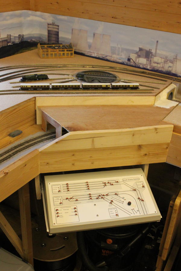
The finished panel mounts just under the baseboard on drawer runners from B&Q. That allows the panel to be put away under the railway when not in use, but to be simply pulled out when needed.
The panel was drawn using visio and laser printed onto sticky back plastic. This has worked well for me before but this time the toner didn't adhere well. I've used clear fablon over the top to protect it.