DCC Architecture
The power to the rails is zoned and has block detection. This is a little more complicated than the minimum DCC installation and is worth expanding on.
The principal elements of this are expanded in later pages on this site, but briefly:
-
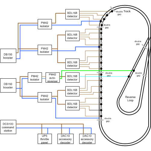
Track power comes from boosters. I have used three: two power the track, and a third powers accessory devices. This ensures adequate power is available; it also ensures that accessory devices are always powered, even if there is a track short.
- PM42 power isolators break the track into different Power Zones. The PM42s act as circuit breakers and ensure that if a short occurs, power is only removed from the local area and not from the whole layout.
- PM42 cells are also used as Autoreversers for reverse loops. Cells used in this way also have a power isolator in their power feed.
- BDL168s are used for Block Detection. This ensures that train movements can be followed around the railway.
- Track sections powered by a PM42 cell are "Double Gapped" at either end of the zones. Each power zone is completely isolated from the next. This is known as "Direct Home" wiring.
- Because of the block detection, the track is powered by a large number of wires each of which is current limited by a PM42. there is no single power "Bus".
For this to work properly, it is important that the PM42 isolators trip at a lower current that the boosters. I've configured mine for a 2.5A trip current, and used a bank of power resistors to adjust the PM42 option switches until that worked. If you have a lower current booster - for example a Zephyr DCS50 or DCS51 - you will need lower trip currents. When properly set up, we get no spurious messages when a train crosses PM42 power zones, or in/out of reverse running zones.
The various modules are distributed around the railway. This table shows where they are:
| Location | Modules | Transformers |
| Fiddle Yard |
DAC20 1 (serial number 8) DAC20 2 (serial number 7) SIGM20 5 (serial number 64) SIGM20 6 (srrial number 65) BDL168 21 |
|
| Clanfield Station |
DAC20 3 (serial number 6) SIGM20 7 (serial number 277) MSC8 1 |
|
| Drop down panel under Petersfield |
DCS100; DB150 1; PM43 33,34; BDL168 22-24; DAC20 4 (serial number 5) |
DAC10 +24v; BDL168 +12v; PM42 +12v; SIGM20 +12v |
| Drop down panel under Eastleigh |
DAC20 5 (serial number 3) SIGM20 3 (serial number 325) SIGM20 4 (serial number 328) BDL168 25 |
DAC10 +24v; BDL168 +12v; SIGM20 +12v |
| Eastleigh (lift up section) | DAC20 7 (serial number 2) | |
| Portsmouth Station |
DAC20 8 (serial number 684) DAC20 9(serial number 685) DAC20 10 (serial number 465) SIGM20 1 (serial number 330) BDL168 28, 29, 30 TXC1 |
|
| Drop down panel under Portsmouth |
DB150 2; PM42 31, 32; BDL168 26, 27; DAC20 6 (serial number 4) SIGM20 2 (serial number 329) |
DAC10 +24v; BDL168 +12v; PM42 +12v; SIGM20 +12v TXC1 +18v |
The modules and drop down panels all have removable power connections so that they can be isolated and if necessary they can be removed from the railway. A 12 pin "chocolate block" type connector that splits into male & female halves has been used. The connections are standardised:
| Signal | Pins |
| Accessory DCC | 1,2 |
| DAC10 Aux Power | 3,4 |
| SIGM20 +12v power | 5,6 |
| BDL168 +12v Power | 7, 8 |
| PM42 +12v Power | 9,10 |
| Booster DCC feed | 11,12 |
| earth | 13 |
The lift-up section for Eastleigh has additional DCC power feeds:
| Signal | Pins |
| Zone B undetected DCC | 1,2 |
| Power feed B50 (25,1) | 3 |
| Power feed B51 (25,2) | 4 |
| Power feed B63 (25,3) | 5 |
| Power feed B64 (25,4) | 6 |
| Power feed M40 | 7 |
| Zone M return | 8 |
This is easy to ignore, because there are no right and wrong ways to do it. If everything is working as it should, then as long as the cables are connected there will be no problem.
In principle, each LocoNet device comes with two telephone style connectors; the wires simply get daisy chained together. However that isn't the neatest solution, and will make debugging difficult. What I chose to do was to split the LocoNet up into sections, with a "bus" joining the sections with wires into different areas "tee"d off from the bus. That way, any one area can quickly be isolated for maintenance or if a board fails.
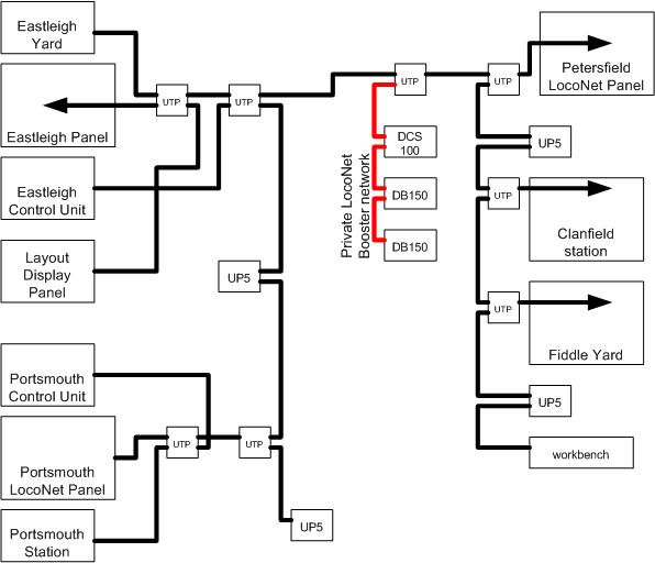
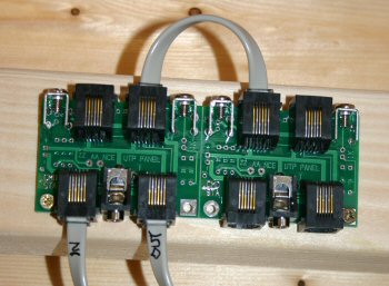
This LocoNet connection is possible because of a module called a "UTP" from Tony's Train Exchange in USA. It provides four connectors all "properly" paralleled with each other. The Digitrax UP3/5 panels do not do that: the outer wire "railsync" signals are not propagated to the front two connectors in the same way. There are also telephone connectors that can be used to parallel up connections but I've never found them very reliable.
| Two UTP panels |
|
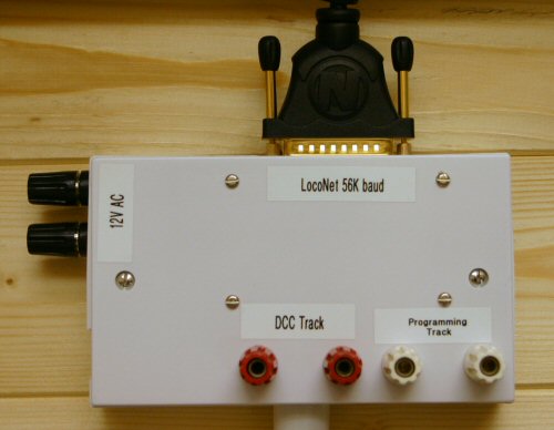
As a finishing touch, I have provided a panel on my workbench with a LocoNet connection, PC connection (via a Locobuffer) and track power, programming track & DC power feeds.