
Locomotives
We have the Tomix "Thomas the Tank Engine" set. Thomas has a decoder installed and (once the chassis was put back together properly) runs quite well. In principle, Thomas could run on a sequence of schedules and visit any through or terminus type platform.
However, there is a catch: Annie and Clarabel have plastic wheels, so we can't add resistors to the axles for detection. The result is, Traincontroller can't detect the train reaching the end of a terminus block if the train is running with Thomas at the rear.
The model seems to be significantly out of scale: it is (probably for artistic reasons) significantly bigger than you'd expect. The running wheels for Annie and Clarabel are 8.9mm diameter (10.2mm across the flanges); typical wheelsets that we can get are nearer 6mm. It would look badly our of scale simply putting smaller wheels in place of the provided ones. as I recall, the axle length is also different from those we have access to.
There could be several solutions, for which the best way forward wasn't obvious:
- Get a suitable wheel set made on a "bespoke" basis by a competent metalsmith
- Find a "near equivalent" that fits the existing axle (1.49mm diameter, approx 1/16")
- Replace the chassis for Annie and Clarabel by a different chassis that we can get wheels for. The chassis is 20.3x62.9mm.
In the end I've gone with the last option, and replaced the chassis using a Peco wagon chassis kit. It is simply araldited to the underside of the Tomix carriage with a 1mm spacer. We can now properly detect presence!
This is the Tomix track cleaning truck, sold in UK by Dapol.
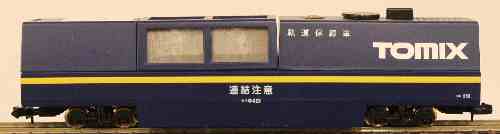
It has been modified for DCC by putting a decoder inside the body. I've used a "function only" decoder I had lying around, but a plain loco decoder would be fine. It is assigned to the loco number of its prime mover loco, and operates as function F1.
This is a visiting locomotive, all the way from New Mexico!
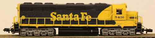
Purchased on a visitto a model shop in USA, as a "I'll need to buy something having been here so long" kind of thing. It pulls the track cleaning truck, which operates on the same DCC number on loco function F1.
A Digitrax DN135 decoder is fitted. This is slightly larger than most N scale decoders nowadays, but fits easily. It is solvered to the PCB with the wire numbers clearly marked; the decoder fits under the PCB.
A lovely smooth running locomotive. It is one of the newest generation of "DCC ready" models with a socket for a 6 pin decoder.
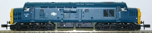
A Digitrax DZ125IN decoder is a "plug in" fit into this chassis. It really is a 2 minute job start to finish.
The couplers have been replaced by Micro-Trains type. The standard coupler is mounted on the bogie, and has been replaced by a 1015-1 "body mount" coupler epoxied onto the bogie. The standard coupler removed by pulling out a pin; that leaves 4 sides of a rectangular box. Cut away the width of that box slightly, and the new coupler will fit. I had to mount it on top of the "shim" that's supplied with it to get it to the height use. I also had to file away the plastic under the buffers to prevent the new coupling fouling the body in tight corners.
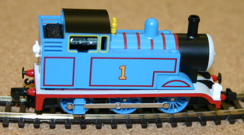
Every railway should have one! This is the Tomix model and it looks the part. Instantly recognisable, and usually popular, Thomas fits in with a railway of any era. I saw the advert and had to have one!I was expecting adding a decoder to be quite easy, having read a description of chipping on the web somewhere. However after removing the body it was clear there have been some design changes! Thomas is now based upon a split frame chassis, and surgery would be required.
The body removed easily by squeezing at the front and rear: that releases two plastic catches and the body separates at the footplate. The footplate itself then lifts off once it clears some indentations (this should be obvious). At that point you are left with a split frame chassis.
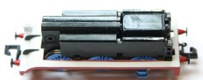
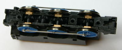
Flip it upside down, remove the three screws and put them in a safe place. The plastic base is clipped at either end near the couplings: the clips can be released using the end of a pair of tweezers at the sides. Lift it off carefully and put it in the safe place. Lift out the couplings and springs carefully, and add them to the safe place. the view will then be like this. Then the wheels can be lifted out.
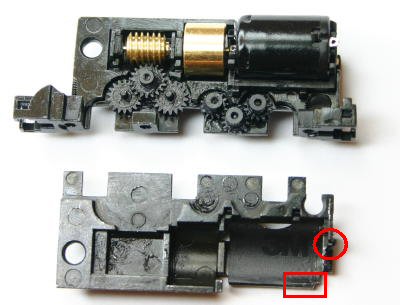
Undo the two screws at the side and the two halves can be prised apart. The motor contacts are connected to the chassis using two tiny springs. you need not put these into the safe place, as they won't be needed (but they look to me very useful for something!)
The decoder installation requires connection to the motor (easy, now we can get at the terminals) and connection to the chassis. The only route I could see for that was to solder to the chassis itself. So:
- file away the "bump" where the springs used to attach (red circle);
- Tin the chassis at a convenient point (red square).
Here's the chassis ready to go back together, with the spacers in place. I forgot to say - be very careful with the gears!
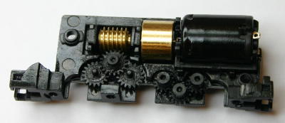
"Reassembly is the reverse of disassembly". Join the 2 chassis sides together: take care to get the plastic spacers around the motor's worm gear the right way around. Then replace the screws holding the chassis side together, and breathe a sign of relief. With the wheels in place, put back the coupling and spring carefully and clip back on the plastic base; then add the 3 screws.
The wheels are quite simple to put in place and quite hard to get the "quartering" right. Because each axle is driven, but the end axles are joined by the connecting rods, it is important to get the end two axles onto the correct gear "tooth". If this is wrong, he will lurch along and it will be necessary to undo the plastic base, lift out an end axle and reinsert it with it turned round slightly so it engages on the next gear tooth.
When the wheels are driven by the "right" gear tooth, he runs smoothly. Don't worry: you will be able to solve this. Run the chassis, and see if the connecting rod doesn't look quite level. Move the front wheel till it ends up right.
I soldered the decoder on after reassembling the chassis. I have an 80W temperature controlled iron, so getting enough heat into the chassis isn't hard. The decoder sits in the top of the cab visible through the windows. The connections to the motor are easy to solder.
And that's it - not so hard after all to do these split frame chassis locos!
Initially I got a lot of track shorts on Digitrax PM42 power managers. I then spotted that only some PM42 zones did this, and a subsequent activity to "balance" the trip currents made the problem go away.