
Locomotives
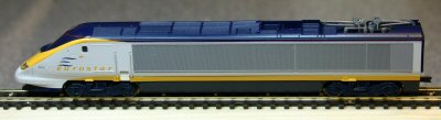
This uses a Digitrax DN163K0B "plug and play" decoder. This installed fairly easily: it is in the form of a PCB to replace the one supplied by Kato. Be careful with the phosphor bronze pickup strips: these can easily get bent, and no longer make contact with the bogie pickups. To get them to work reliably, they need to be bent in a way that seems counter-intuitive; the body affects their shape too.
The cab lights needed to be changed: the while LED supplied is in the rear (red) light position. The PCB has pads for a front light, but the leads need to be extended. It can be done, though!
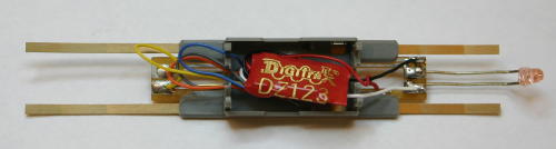
The trailer cab could be modified with the same P&P decoder, but I used a more conventional DZ123 as there is a lot of space available.
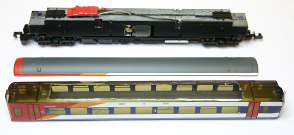
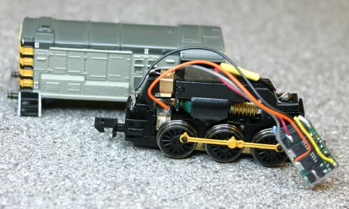
The chassis with the plastic shell removed (Use a fingernail to unlatch the tiny clips at the bottom edges, then it simply lifts off). The motor assembly simply lifts out: the driveshafts to the bogies are a push fit into the flywheels. (Getting them back in is fiddly, but that's all).
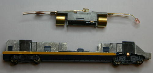
The decoder replaces the PCB mounted above the motor; no wiring or drilling involved. But take care of those long phosphor bronze strips!
This is the PCB from the trailer cab. The space where the motor would go is free, allowing a decoder easily to fit. A 2 function lighting decoder would do, but I didn't have one!
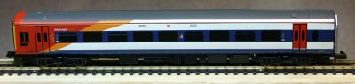
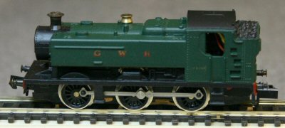
I don't know why but I just like this model. It is a simple chassis with no bells and whistles (OK, no lights) but it runs nicely.
This is a split-frame chassis, and there are no wires to intercept. I was able to get the basic instructions for this from the web, courtesy of Smallphry: all I had to change was housing the decoder itself.
The body lifts off: it is only held on by two tiny clips at each side. Remember which is the front - it doesn't go on both ways! Mark carefully the position of the two plastic mountings above the bogies. There are several indentations here, for several different models. It will be a lot easier to find out BEFORE removing screws. Note too which way the "dimples" in those plastic mounting are (towards the chassis centre for this model).
Then disassemble the chassis. Remove the two screws securing the "undercarriage", and remove the two screws holding the body sides together. Keep all of the bits together: food containers from the local Chinese takeaway seem the ideal size for a lot of stripped models.
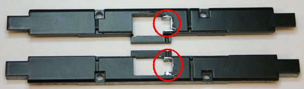
The pickups on the bogies contact onto the chassis sides. The motor used to get its power directly from the chassis sides. To insulate it, some metal needs to be routed out. I used a handheld "Dremel" tool with router attachment which easily managed the task. The material to be removed is marked. After doing that, clean thoroughly with a brush or air duster.
The decoder orange and grey wires now need to be soldered to the motor brush retaining clips. The wires then thread upwards through the middle of the chassis without further ado. I wasn't satisfied about the insulation of the brush one one side of the motor (the brass clip was VERY close to the front edge of the plastic moulding) so I also used small pieces of Kapton tape to insulate thoroughly.
The chassis can then be reassembled. "Reassembly is the reverse of disassembly" is easy to say: but this is fiddly. It was a lot easier after I laid the chassis side onto a piece of 2mm thick balsa: this allowed the bogie to hand downwards slightly and straightened out the various bogie mountings.
The decoder red and black wires need to go to the chassis sides. The two retaining screws are a good way to make contact; I soldered the wires to small cut down washers, and scraped away the paint, then simply put the washer under the screw head. The decoder fits nicely in the roof: but making the hole in the roof wasn't as nice. The very top is separably moulded, and can be removed (as I discovered later). The main body has an "inner roof" that is a snug fit to the chassis: a hole needs to be cut for the wires and decoder.
To cut away the top, I used the Dremel again with a milling cutter. This cut easily, but tended to melt the plastic leading to a lot of stuck-on swarf. With practice this could have been neater! The roof can then be glued back on, and the whole then clips back.
I used a Digitrax DZ123 decoder: they are quite small and perform well. In this installation I forgot to mark the front before starting; when tested the train ran backwards when "forward" was selected on the decoder. I'm not opening it up again: so the simple solution was to change CV29 to 7.
This was my very first loco, purchased a good 5 years before I had track to run it on! The plan was "when a DCC decoder goes in this, they'll go in anything".
I've recently re-done the decoder installation. First time around I isolated the pickup strips using Kapton tape. That seemed simple and worked, but it also created play in the wheel axles, and the engine ran erratically. I've redone the installation using the DCC Supplies"DiGiHat" plastic bush to isolate the bottom motor brush: this is simple the pickups are now connected back to the chassis. the DZ123 fits into the back of the cab: I had to remove its red heat-shrink and re-insulate with Kapton tape.
For those interested, the decoder installation is now essentially identical to that for the class 08 shunter.
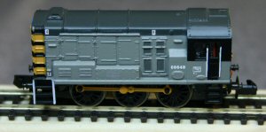
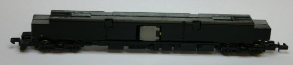
This is one of the older models on the railway. The chassis is a single casting and the motor needs to be isolated from it. The model runs OK at low speed, but at high speeds (which are ridiculously fast for this model) the decoder doesn't control it properly: I assume it is getting poor pickup and can't decode speed commands.
A decoder does fit into this model, but it is tight. I used a TCS M1 decoder, located vertically in the cab. I had thought it would fit horizontally in the cab between the shell and the chassis, but it seems not quite to fit. With the capacitor removed, the remaining wires can simply be soldered in place: use the capacitor's wires for chassis and top brush connections.
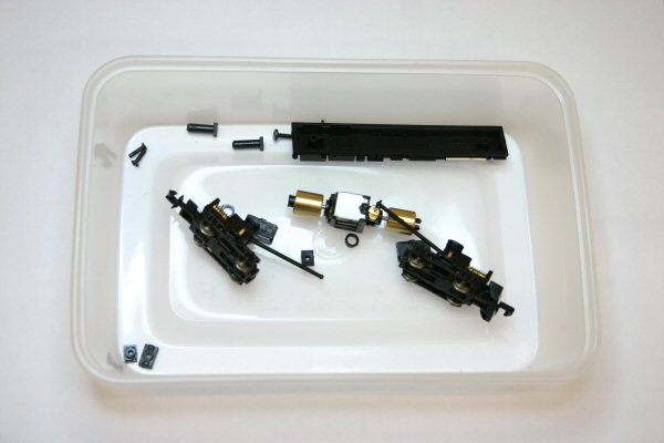
The chassis opens easily by removing the two screws at the front sides. CAREFUL: don't lose the coupling or its spring. I've used the DCC Supplies"DiGiHat" plastic bush to isolate the bottom motor brush: this is simple to use and results in a quick installation.
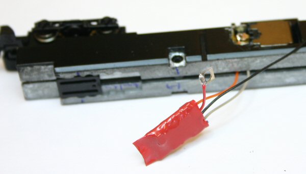
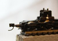
Here is the chassis after the DiGiHat has been installed. The plastic DiGiHat bush is under the bottom brush clip, to which the orange wire has been attached. The heat-shrink is threaded over the wire, the wire is soldered to the brass clip then the heat-shrink sleeving is heated up. I use a paint stripper gun for this.
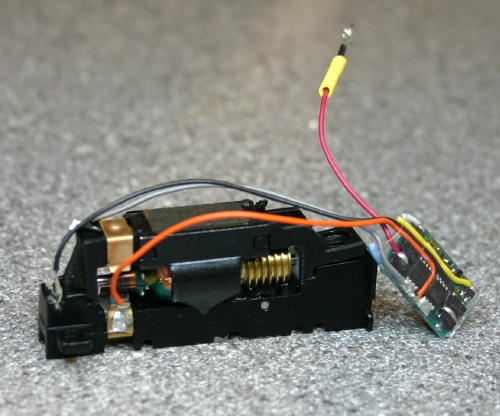
The black wire goes to chassis (use the cut-off capacitor lead); the grey wire goes to the top brush clip (also use the cut-off capacitor lead). The red wire goes under the nut on the thin bolt, still to be re-installed on the right hand side.
Here is the chassis ready to go back; note the red wire attached now to the wire going under the nut.
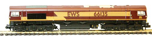
The EWS Class 66 is a Graham Farish model and was one of the first I purchased that included provision for DCC decoder installation. There is a circuit board along the top of the chassis; remove two clips, solder the decoder wires, rearrange the wires to the end lights (so as to make room for the decoder) and hey presto - a DCC equipped loco. A Digitrax DZ123 fits and works fine.
The locomotive lights are operated using the F0 function. The large fan vent indicates the front of the locomotive.
I've added Micro-Trains couplings to the bogies. A #1130 kit (long shank) fits well, and slightly increases the coupled length to the rolling stock. A shorter coupler would probably foul the buffers, but now I'm mounting them lower it could be reconsidered. See how the top of the coupler insert has been shortened so as not to foul the buffer beam:
I had problems at first with fouling that resulted in the bogie's drive from its work gear not meshing. The coupling was fouling the buffer beam, and pushing the bogie downwards at the end of the body. With the coupling mounted to the bottom of the pocket it is less of a problem now.