
This is where my time has gone since Christmas!
I agreed to look into how to make a control console for PowerSDR, so that you can control it with "knobs and switches" rather than a PC keyboard & mouse. It's always been possible for SDR to have that (just look at pihpsdr or the IC7300); but PC based SDR has always had the question of "how do you connect the controls". John Melton G0ORX described a way to do this a few years ago, but no-one had taken it further.
It's easy to connect serial ports to a PC, using USB; and Arduino microcontrollers already have that connection. Plan A: devise a suitable language to describe the control interactions (LED on or off; encoder step clockwise or anticlockwise; pushbutton pressed or not) and send messages from the Arduino. Then modify PowerSDR to read those messages. I had the Arduino part working in November.
But.... changing PowerSDR would be a huge step. I'd need new setup screens to configure all of the settings. So I decided to try John's approach, and use the existing CAT command structure that's already programmed into PowerSDR. I was keen to be able to replicate the "user interface experience" of a high end radio - for example the FT1000. I've repaired enough of them after all! I wanted something that would make my friends want to use PowerSDR for a contest, rather than their FT1000s.
The principle was sound. I looked at a number of high end radios to see what their user interfaces had - looking at the FT1000, IC7610, IC7300, FT9000 and the new Flex Radio Systems "Maestro" console. What I found was:
- A high quality tuning knob
- A clear display
- 5-20 indicators (like LEDs)
- 5-10 other rotary controls
- Quite a lot of pushbuttons
The first two were by far the most critical. An FT1000 tuning knob has around 600 VFO steps per revolution; you can turn it at 4 turns per second and it keeps up. Users expect that. I've also come to like the "dual shaft" rotary encoders where you can change the lower and upper edges of the IF filter passband using concentric knobs, like on the TS590S and IC7300.
Next step: I've approached this as a joint project with Kjell Karlsen LA2NI (developer of several of the HPSDR projects). Kjell agreed to make the PCB and design to fit an enclosure; I've done the Arduino software. We settled on a Nextion touchscreen LCD display; an optical encoder, 4 dual shaft encoders and 17 pushbutton switches (some of which are illuminated).
The "user experience" with the tuning knob was important to replicate. For the FT1000 it can generate nearly 2500 steps per second. If I use CAT commands to send that many "VFO step" commands I end up needing to send 17000 ASCII characters per second; the upper limit for normal communication, even assuming the software can keep up, is around 10000 characters per second. Instead I've opted to "batch up" the VFO steps and send a message every 10 milliseconds saying how many steps have happened. It uses far fewer characters, far lower message rate and doesn't load PowerSDR. Critically, it works - no lag - and sounds just the same when you "tune through" other signals. That meant adding new CAT commands to PowerSDR, and in the end I added several all in one batch; they've been included into the 3.4.9 release.
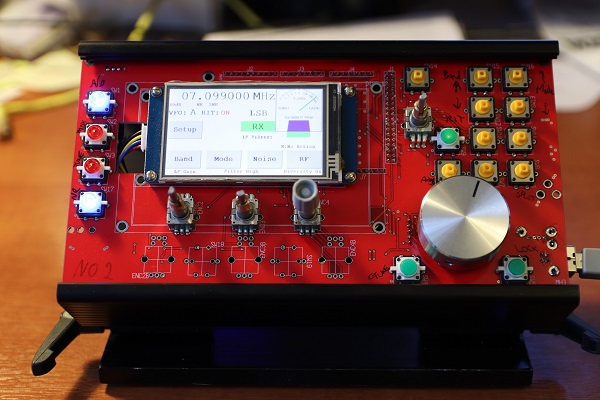
So here is the prototype: working fine with PowerSDR, and "feeling" like a conventional radio. Most of the commonly used controls are on the front; you can switch between VFO A and B (or have a second console, we think...). The display shows current settings including IF filter position; additional screens can be used for frequency entry, and for other less often used settings. All of the controls can be reconfigured, if you want different functions on them, using a setup screen.
The design files and software are on GitHub:
Come and see it at Friedrichshafen!
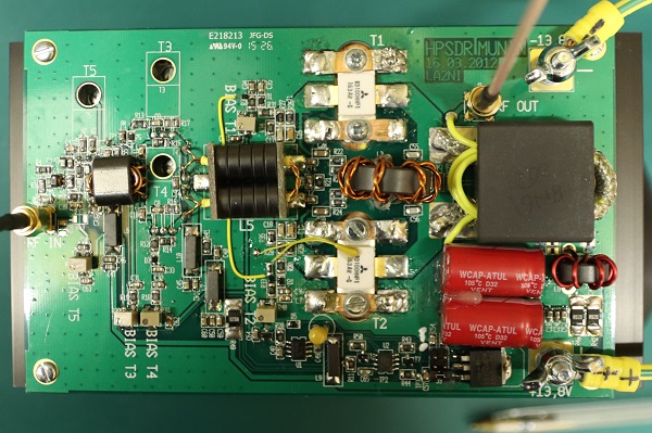
A long time in coming, I suspect... Munin is the 100W amplifier developed for HPSDR. As well as the 100W final output stage, includes a driver stage and a pre-driver stage. The pre-driver isn't normally assembled (and I've had to guess at some of the component values); but when it is, the amplifier apparently needs around 0dB in for 100W out. I collected the parts to make the Munin over last Autumn and completed a lot of the assembly at Christmas.
You can find a lot of information about Munin with links to all of the design files etc here.
There was nothing particularly difficult with the construction, once I had all of the components. The ferrites, and RF output transistors, came from US suppliers RF Parts and Kits and Parts. The drivers (RD16HHF1) came from ebay. The "middle" RF transformer was made from ferrite beads and copper tube, rather than buying the CCI transformer - simply because the shipping cost was approx. 3x the transformer cost. My ability to tap holes in aluminium has been brought into question - several holes ended up with stripped threads. 3 half turns clockwise, one half turn back was the rule and I should have stuck to it.
Testing got off to a poor start: I was unable to apply power to the board with it appearing dead short to the power supply. By removing the ferrite beads carrying power to each stage individually, I was able to isolate the problem to the intermediate stage. It turns out that the RD16HHF1 devices from Ebay were not genuine Motorola devices: instead they were diodes. The data code markings were different from what everyone's image show; I think they were counterfeit devices. I've never once had that before. Two new devices that were by now ex stock in UK, and the amplifier worked fine.
I've been able to prove I can get 100W from the amplifier. I haven't yet done linearity tests; I've equipped myself with a dummy load to which I've added a 30dB coupler ready for that (see below). I really don't have any more excuses... I've found that PowerSDR can generate a two tone signal, and with approx. 10dBm PEP each carrier is at 4dBm. That's correct: sometimes they will add in phase, doubling the voltage and hence quadrupling the power. Once I've determined the power required for 100W out, I can make the attenuator board and package everything up. Oh.... and fix the software bug that makes the Arduino crash; my money is on an array reference out of range.
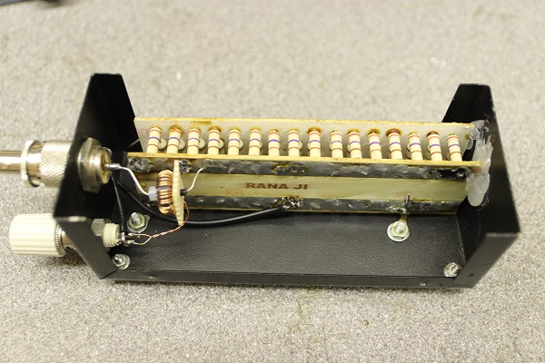
I've made a modified dummy load: start with a 100W dummy load from ebay, and ass a 30dB coupler and you have a load capable of taking full power and giving you a signal it's safe to feed into a spectrum analyser. the 30dB coupler is simple an FT50-43 toroid, with the input power on a single wire through the centre of the toroid and 32 turns of 25SWG wire wound onto the core as a secondary.
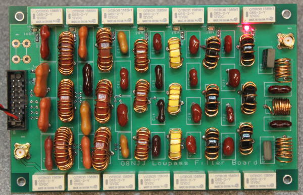
Nothing to do with software defined radio, but…. every transceiver needs TX filtering, and mine will be no exception. You can buy filter boards, and my original intent had been to re-use one from ebay salvaged from a scrapped transceiver. Then curiosity took hold. I’ve ended up with a fully working filter board, controlled by my Arduino, but as usual there’s been a story along the way!
It’s generally accepted that an HF transmitter needs 7 low pass filters, although the exact splits around the WARC bands does vary. Most seem to be 5 pole filters – typically three capacitors and two toroidal inductors. Air cored inductors are sometimes used for 50MHz. The power dissipation is small (because you’re trying to pass HF, and remove less than a watt of harmonics) but the capacitors do see a high voltage (around 70 volts RMS at 100W) meaning you need special capacitors – either high voltage C0G dielectric ceramic, or silver mica. 5 pole filters do give good enough rejection of harmonics if the filter cut-off is just above the band, but using a filter for two bands (eg the 14MHz filter also covering the 10MHz WARC band) makes this harder. I decided to use 7 pole filters, on the basis they roll off faster.
There are lots of free computer programs for filter design. The two kinds are filter synthesis (i.e. designing the inductor & capacitor values for a given filter specification) and analysis (where you calculate the actual behaviour of a set of components). You need both. I used RFSim99 because I preferred its user interface, but QUCS is regarded as a standard. (I found filter synthesis gave slightly different results between the two, but the analysis simulations were identical).
My design approach was:
- Use filter synthesis to find the idealised component values needed, setting the “corner” frequency of the filter above the highest TX frequency. (I aimed for the -3dB point being 1.4x max frequency). This gives you a set of component values, that won’t match anything in a catalogue.
- Find the nearest “real” capacitor and inductor values. Capacitor values are usually E12 1-1.2-1.5-1.8-2.2- etc values. Inductor values depend on the number of turns wound on your chosen toroids. I started with a plan to use T50-2 and T50-6 toroids; in the end I also added T68-2 at low frequencies (the larger core allowing more windings) and T50-10 at high frequencies (the lower permeability allowing more turns). I also opted for air cored inductors at 50MHz, but this may be a sub-optimal decision. You can find inductor calculators here, and a table of toroid inductances here.
- Use filter analysis to find out the true behaviour of the circuit you’ve arrived at. My aim was <0.1dB in-band loss, ~40dB loss at 2nd harmonic and 60dB loss at 3rd harmonic. If the filter doesn’t meet these specs, change the components values a bit, change toroid cores or move the “corner” frequency a bit. Remember that the PCB traces may add ~25nH inductance, so make the target inductance slightly smaller than needed. You can find inductor calculators here, here and a table of toroid inductances here.
- Solder them together and measure the performance. I prototyped every filter before soldering into the PCB. All the inductors use 22SWG wire, which will happily carry the 1.4A RMS current at 100W.
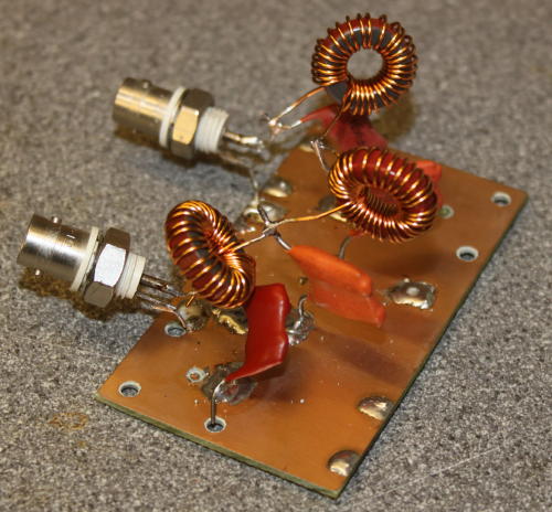
I only had problems with one filter – 21MHz – which was eventually traced to having used the capacitors from the 14MHz filter. The 50MHz filter has been optimised by compressing/expanding the windings to adjust the inductance, but it isn’t perfect.
The whole seems to be a good solution. I’ve measured the in-band insertion losses, and the attenuation at each harmonic. I also operated each filter with 100W of CW “key down” to see if power dissipation was a problem. Nothing seemed to warm up, so imminent destruction if the filter isn’t likely.
Anyone seen my Red Pitaya? Is that it, under there?
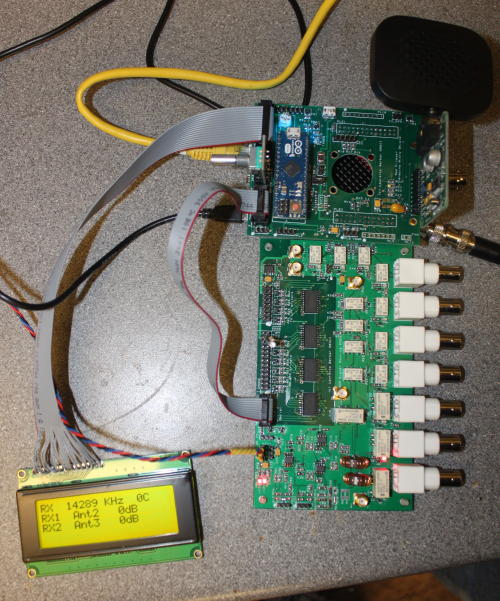
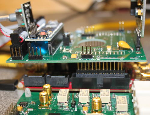
The "shield" is a new PCB that sits on top of the Red Pitaya. It replaces the original hand-wired Arduino shield, and acts as an interface to a number of other things:
- The Arduino itself plugs in - I switched to an Arduino Micro
- The audio codec plugs in - Using the MIKROE-506 unit
- The LCD and rotary encoder plug
- the filter boards will plug in, when I've made them
- The relay board plugs in
- The Munin amplifier will connect too
Most of the board worked straightaway... except for the Codec board. the Codec, it seems, doesn't "like" the 3.3v to 5v level translator chip between the Red Pitaya and the Arduino.. I've not understood what it's not happy about - the logic levels look fine, and the timing is essentially identical - but with the level converter powered, the Codec won't respond to I2C commands. In the short term I've removed it and bypassed the level converter, but I'm not totally happy with that arrangement - it means the Arduino is only getting logic 1 voltages of 3.3v which marginally meets the specification. i'd be a lot happier with a "proper" logic 1 level.
I've included space and mountings for a fan, but I don't think it will be needed.
Next stop - the Munin amplifier. I have most of the components now - just need to get on and make it.
I never intended this to be an ongoing blog, but here we are with update 9.....
My design puts the interface to the RF hardware, and a simple user interface, into an Arduino. This leaves the ARM processor in the Red Pitaya to deal with data transfer, ethernet interfacing etc. In that role it's grossly underutilised, and could easily accommodate the hardware interfacing etc; but it has limited I/O resources available.
Why? Because I wanted to use a hardware interface different from the "Alex" interface. My design allows the settings available through the HPSDR software architecture to be used with different hardware. I wanted to re-use an existing bandpass filter board on receive, for example. Ultimately I could have put all the code including user interface etc into the Red Pitaya, but the code would deviate quite substantially from Pavel Demin's code at that point. This way, there is a "clean" interface between the two.
The Arduino to Red Pitaya interface is I2C. I2C is a simple, bidirectional bus using two wires. Pavel Demin has already used the I2C interface for the Alex interface; I've made my Arduino "look" like 6 registers each taking 16 or 24 bits of data. The Red Pitaya uses 3.3V logic, and the Arduino uses 5V; I've used a level translator IC between the two, which also includes the pullup resistors needed to make I2C work.
The new "registers", all at interface address hex 40 (64 decimal) are as follows:
register 1: RX1 Frequency (16 bits + ID)
register 2: RX2 Frequency (16 bits + ID)
register 3: TX frequency (16 bits + ID)
register 4: Open Collector Outputs, antenna settings (24 bits + ID)
register 5: RX attenuation (24 bits + ID)
register 6: TX attenuation (16 bits + ID)
I've also published the code on GitHub: link.
The I2C interface worked first time. I started with code in the Arduino simply to print characters to its serial terminal and changed the sdr-transceiver-hpsdr.c code to send the appropriate settings to the new registers. I was able to debug the code at that point by checking the messages; then I updated the Arduino code to set the various hardware registers appropriately.
A change that I did need to make was the TX strobe from the Red Pitaya to the Arduino. When all the code was running that worked fine; if the server program on the RP wasn't executing, or the RP was powered off, then the Arduino entered TX mode. I was using the same level converter IC; changing to a simple transistor driver solved the problem.
My Arduino provides a simple user interface with a 4x20 character LCD display. on Receive and Transmit it provides a simple front panel display of how the radio is configured. There is a debug mode allowing you to changes all the hardware settings to test the radio hardware. For convenience and safety, that needs a jumper to be removed to prevent inadvertent use of the mode. The display includes simple bargraph display of forward power and VSWR, with a crude "peak hold" for SSB forward power. It's not a "proper" user interface; but it will tell me what the radio is doing.
I had originally intended to have a "shield" on the Red Pitaya and another on the Arduino. I'm thinking now I'll make a single shield that mounts onto the red Pitaya, and the Arduino plugs into the top: The "Arduino Micro" is designed to be mounted like that. The shield will need connections for:
- Red Pitaya low speed analogue I/O (eg VSWR monitor)
- Red Pitaya GPIO (I'm not using these, but you never know)
- Audio Codec
- buffered TX strobe from Red Pitaya (eg for transverters)
- 5V power connection, with jumper to Arduino 5V input
- Transistor/FET buffer for TX strobe
- I2C level translator
- Arduino low speed analogue inputs
- Arduino SPI serial out to RF hardware
- Arduino interface to LCD (inc bias potentiometer)
- Arduino interface to rotary encoder
I'll try to make the connectors match the other end (eg current monitor and TX strobe matching the Munin pinout). This will tidy up the connections internally no end!