
Using CAD
The baseboards were designed using the CAD program, after sorting out the track plan. The advantage of using the same program for the design is that you can (as far as possible) avoid having timber underneath point motors etc.
I used 2 "layers" in the program for baseboard designs: one for the main baseboards, and one for the higher level sections. From these designs I was able to print out the design, then do gown the garden and make it without needing any further input.
XTrkCAD is excellent for the "railway" part of the design process.Unfortunately it has no real support for capturing the electrical design
I implemented a partial "fix" for this by using some simple graphics to show track breaks and power feeds. On a railway with well over 100 power feeds, that has been invaluable.
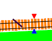
The track "break" speaks for itself. It is simple a line. There is a feature in XTrkCAD to show track breaks, but they didn't print out; that may have been fixed by now. The power feed symbol is a pair of filled polygons, one of which has a number attached to it (and which displays if the diagram is zoomed in far enough). However, these are only graphical annotations; there is no association to the track itself, and no way to check for shorts.
A very useful feature would be to highlight areas on track in a different colour, to be able to show booster districts and power management zones. I haven't been able to find a way to do that.
I've used XTrkCAD to produce a fairly thorough plan for the mechanical parts of the railway. I've also used it partly to create an electrical plan, but it is less good at that.
I don't have much experience of model railway designs, and had no real idea how much track would fit into what space. The choices I say were either to "try it and see" or try to get a stronger up-front design. I chose a CAD approach, because I'm used to similar tools for other things; it was a choice that was definitely right for me!