
XTrkCAD is excellent for the "railway" part of the design process.Unfortunately it has no real support for capturing the electrical design
I implemented a partial "fix" for this by using some simple graphics to show track breaks and power feeds. On a railway with well over 100 power feeds, that has been invaluable.
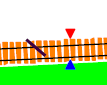
The track "break" speaks for itself. It is simple a line. There is a feature in XTrkCAD to show track breaks, but they didn't print out; that may have been fixed by now. The power feed symbol is a pair of filled polygons, one of which has a number attached to it (and which displays if the diagram is zoomed in far enough). However, these are only graphical annotations; there is no association to the track itself, and no way to check for shorts.
A very useful feature would be to highlight areas on track in a different colour, to be able to show booster districts and power management zones. I haven't been able to find a way to do that.