
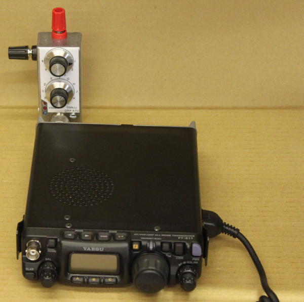
This is a very simple ATU, designed for portable operation with an FT817. There's no point having a small transceiver if you need to carry lots of kit to use it: so this was designed down to a size. I liked the "Wonder Wand" style of ATU, but thought I'd have a go at making my own.
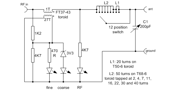
The ATU was designed to fit a 9cm x 3.5cm x 3cm diecast box. The RF input is via an SO239 connector, which connects through a male-to-male adapter straight onto the back of the FT817. An "L match" ATU circuit is used, with a 12 position tapped inductor and 200pF "polyvaricon" capacitor. Particularly because of the latter, the power is limited to a few watts maximum.
A simple LED indicating VSWR display is also used: the idea is that the LEDs light if reverse power is present, with one LED being more sensitive to allow "nulling" of reverse power. This uses the design by DF3OS.
In keeping with the "Wand" style ATU, I tried it out with a telescopic antenna. After shopping around, the longest I could get was around 1.2m which you will realise has too small an aperture to be usable on HF (although it worked nicely on 2m, and could be matched on 20m and up). A length of wire proved much better.
There is a "word of warning" with ATU design. Make sure that the switch selecting the number of turns on the inductor shorts out the unused turns. Without that, the unused part can resonate. Mine did, at 21MHz; it took a while to work out why it wouldn't load up on that band. with the unused turns shorted out, its behaviour was transformed.
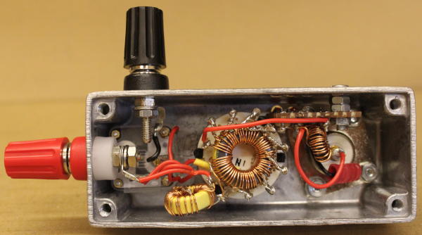
Construction
There aren't many components involved, so cunstruction is simple. Most of the inductor is wound on a T68-6 (yellow) dust iron toroid core. This has 50 turns with taps at 2, 4, 7, 11, 16, 22, 30 and 40 turns. Remember that the switch alnso needs to select the 50th turn, and the start of the coil (i.e. the "0"th turn). Because I couldn't fit all of the turns onto one core, a further 30 turns on a smaller T50-6 toroid is used to provide additional inductance if needed. With a larger toroid, it may have been possible to get it all onto one core; try a T80 or larger core and aim for 60 turns total if you wish to experiment.
The VSWR indicator circuit has a small ferrite FT37-43 core, the primary of which is just a single wire passing through the middle. It is constructed on veroboard.
I don't know how people test and calibrate ATUs. Ideally I suppose you could pake up various "test loads" with coils, capacitors and resistors and see if they match. My approach was simply to test the match into 50Ω and into a small wire antenna.
In Use
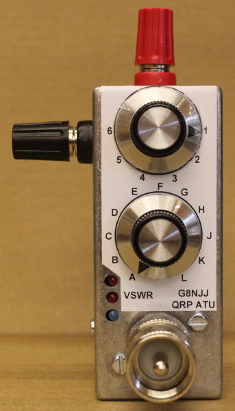
For such a simple circuit it does seem to be remarkably effective, and it is easy to use. The inductor taps are marked A-L and the capacitor is marked 1-6. The VSWR indication isn't very effective (two LEDs can never be as good as a moving meter needle, but there's no way one of those would fit the box). But what I've found very effective is to pre-measure the required settings for a 5m vertical antenna and go back to them - it is pretty repeatable. They are marked on the side of the unit with a dymo tape.
| Frequency | 50 Ω load | 5m whip antenna |
| 3.6MHz | L4 | poor! |
| 7.1MHz | L4 | C6 |
| 14.2MHz | K4 | G3 |
| 21.2MHz | J4 | G5 |
| 29MHz | K5 | G6 |
| 51MHz | K5 | H5 |
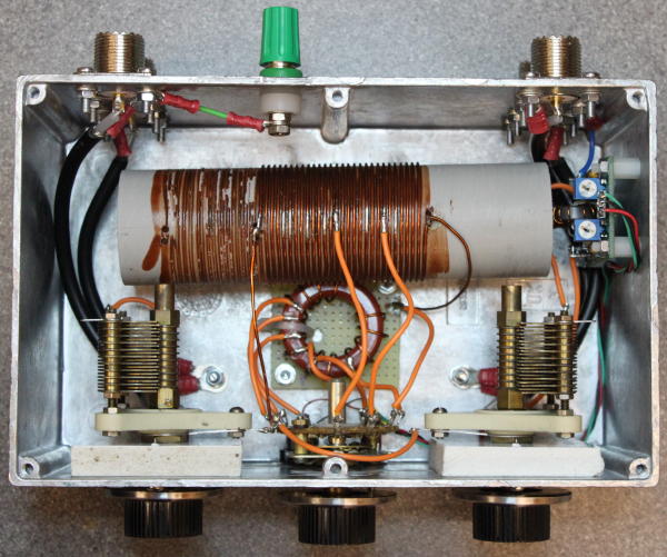
My first project: a simple antenna tuner for the HF bands. The modern approach to antenna tuners seems to be to use the "T" match (a highpass construct) rather than the "Z" match (which is a lowpass filter). General wisdom seems to be to have capacitors approximately 250pF, and an inductor 25-30uH.
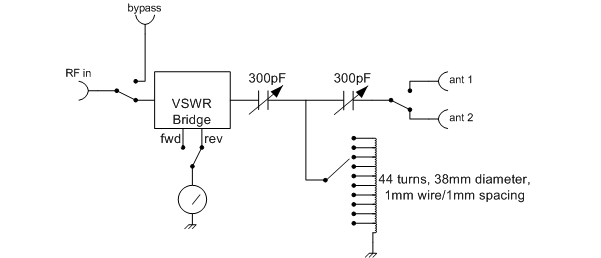
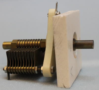
Sourcing the capacitors was a problem: I can't find anyone that makes variable capacitors any more! I purchased some from J Birkett in Lincoln, but these had very small air gaps which would limit the usable power. Eventually I found a pair of 300pF (ish) capacitors at a Rally. The "T" match design requires that the capacitors be insulated from ground. I mounted mine onto a thin piece of plastic material with a partly bored hole for the mounting nut. The knobs are calibrated 0-6, with 0 being full capacitance and 0 being exactly unmeshed.
The inductor was wound on a 5 inch piece of 38mm drain pipe using enamelled copper wire 1mm diameter. I aimed for double spacing using another piece of wire as a spacer, which was later removed. The whole was varnished to hold the wire in place. The VSWR bridge was originally to be home made, but I'd purchased a universal VSWR bridge kit while purchasing toroids and in the end I used that for convenience. I have a 10 position rotary switch - modified from a 2 pole 5 way switch giving 9 positions plus open circuit.
The conventional wisdom is that the inductor should be evenly tapped. I tried and fund that I almost never needed beyond the 12th turn, and from 14MHz I was always on the 4 turn tap. I retapped the coil with the following results, measured with an MFJ259B antenna analyser:
| Switch position | Turns | Inductance |
| 0 | 2 | 0.8uH |
| 1 | 4 | 1.6uH |
| 2 | 6 | 2.4uH |
| 3 | 8 | 3.3uH |
| 5 | 12 | 5.3uH |
| 6 | 16 | 7.5uH |
| 7 | 21 | 10.6uH |
| 8 | 27 | 14.6uH |
| 9 | 34 | 20uH |
| 4 | 44 | 29uH |
A tiny "battery indicator" moving coil meter was used for tuning indication. It isn't intended to provide a calibrated measurement. The ATU was assembled into a diecast box, and spray painted. Mysteriously the colour looks remarkably like that of my old car.
Loading into 50Ω and into my longwire antenna was as follows (recorded as C1 - L - C2):
| Frequency | 50Ω | End fed antenna |
| 1.9MHz | 0-8-0 | 1-9-3 |
| 3.65MHz | 4-7-4 | 3.5-6-3 |
| 7.05MHz | 4-4-3.5 | 4.2-3-2.5 |
| 10.1MHz | 4.5-2-4 | 3.8-1-3.8 |
| 14.2MHz | 4.5-1-4.5 | 2.5-0-3 |
| 18MHz | 2.5-0-1.8 | 4-0-0 (poor) |
| 21.2MHz | 2.8-0-1.8 | 4.5-0-0 (poor) |
| 24MHz | 2.5-0-1 | |
| 29MHz | 0.8-0-0.2 | no match |
Clearly there is a problem at high frequencies. The stray inductance makes it hard to measure the coil inductance, especially with the switch and wiring in place. The coil may need more taps down the "bottom" end, and there may not be enough steps available.
Back to the drawing board!
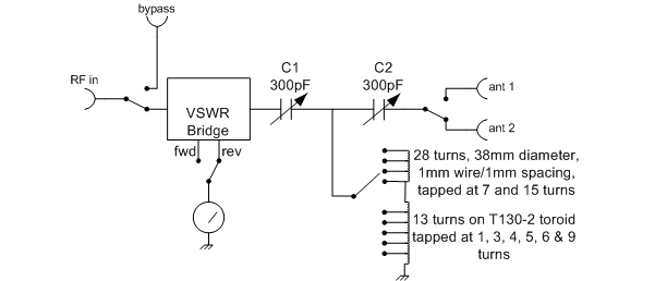
This follows on from the earlier attempt! My first ATU wouldn't tune at the higher frequencies, because there were not enough taps on the inductor to select small values of inductance. time to do some design, and not guesswork!
I've noted that some designers use two inductors - one for low and one for high frequencies, I found an on-line T match simulator program and worked out inductance values both to feed a 50Ω load and to feed my longwire antenna. This suggests that the inductance values need a lot of choice at the "low inductance" end, for example:
0.2, 0.3, 0.4, 0.5, 0.6, 0.8, 1.1, 1.5-2, 4-5, 16-20 (all microhenries)
I shortened my 38mm inductor to 28 turns withs taps at 7 and 15 turns; and I wound a 13 turn inductor on a T130-2 iron dust toroid core. That has taps at 1,3,4,5,6 and 9 turns.
The results now lets me match well on all bands including 50MHz (I've no idea how much power is being coupled out, as opposed to being lost in the toroid though).
Sourcing the capacitors was a problem: I can't find anyone that makes variable capacitors any more! I purchased some from J Birkett in Lincoln, but these had very small air gaps which would limit the usable power. Eventually I found a pair of 300pF (ish) capacitors at a Rally. The "T" match design requires that the capacitors be insulated from ground. I mounted mine onto a think piece of plastic material with a partly bored hole for the mounting nut. The knobs are calibrated 0-6, with 0 being full capacitance and 0 being exactly unmeshed.
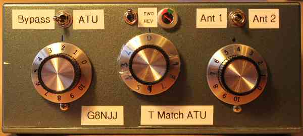
The VSWR bridge was originally to be home made, but I'd purchased a universal VSWR bridge kit while purchasing toroids and in the end I used that for convenience. A tiny "battery indicator" moving coil meter was used for tuning indication. It isn't intended to provide a calibrated measurement. I've adjusted the forward and reverse power meters to give a mid-green indication with 5W.
The ATU was assembled into a diecast box, and spray painted. Mysteriously the colour looks remarkably like that of my old car.
Loading into 50Ω and into my longwire antenna was as follows (recorded as C1 - L - C2). These values are up on the wall, and are remarkably accurate when I "revisit" a band allowing simple tuning:
| Frequency | 50Ω | End fed antenna |
| 1.9MHz | 1.2 - 4 - 1.2 | 0.2 - 4 - 3.2 |
| 3.65MHz | 0.8 - 1 - 0.8 | 2 - 1 - 1 |
| 7.05MHz | 1 - 3 - 0.9 | 4 - 2 - 1.8 |
| 10.1MHz | 2 - 5 - 2 | 4.6 - 3 - 4.1 |
| 14.2MHz | 1.5 - 7 - 1 | 3.7 - 7 - 3.9 |
| 18MHz | 1.1 - 7 - 0 | 4.5 - 7 - 2 |
| 21.2MHz | 2.4 - 8 - 1 | 4.9 - 7 - 4.2 |
| 24MHz | 2.5 - 8 - 0.8 | 5.3 - 8 - 4.3 |
| 29MHz | 2.5 - 8 - 1.8 | 4.7 - 9 - 4 |
| 50MHz | 5.2 - 9 - 5.1 | 5.8 - 9 - 5.3 |
A good outcome; I've declared it "finished".