
Crossovers (i.e. a diamond crossing) need to be wired carefully. The crossing itself will have four dropper wires: one for each outer rail, and one for the frog at each end. The way power is applied to these depends on which route a train will be taking. There appear to be two commonly used approaches:
-
Apply constant power to the outer rails, and use an autoreverser to feed the frogs;
- Use a relay to switch the power depending on the setting of the point feeding the junction.
In my case, the crossovers are always on 2 track main lines with an adjacent point connected to the "crossing" route. In a real railway, this point would only be set to the crossing direction when the signalling system was about to let a train run through the crossing route; otherwise the point would be set to "straight on". When the crossing route was selected, a signal would prevent traffic on the other line reaching the crossing. My railway will have all of those constructs; consequently it is practical to use the point state to determine how the crossing is powered.
Consider the crossover above. When the point is set "straight ahead" (in this case THROWN) then the crossing needs to be wired for the other main line. when the point is set to branch away (in this case CLOSED) then the crossing needs to be wired for the point. In both cases the point frog needs to be powered too. The relay is only energised when the diverging route on the point is selected, to maximise relay life (probably it doesn't matter; but having them powered most of the time seemed daft). This leads to five separate track regions (A-E) that need to be powered as follows
| Track Segment |
When Point Thrown |
When Point Closed |
| F | C27 blue | C27 red |
| A | G29 blue | C27 blue |
| B | G29 red | C27 red |
| C | G29 blue | C27 red |
| D | G29 red | C27 blue |
To make this happen, I have used three 2 pole changeover relays: the CML Electronics RLY2. These are interconnected according to the principles described here. The whole lot is assembled onto a small timber batten, with the relevant wires ready to connect to the layout; this can be tested before installation.
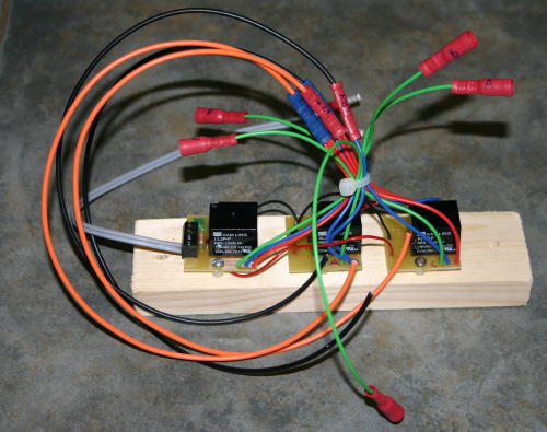
Coming into this bundle are power feeds from two track sections (orange and black wires); going out are five track feeds in green. The grey pair connects to the switch in the point motor to operate the relays.
Not shown is a 12v DC power feed, which goes to the left hand relay board. The other two are simply daisy chained from it.
There are detailed crossover diagrams for each junction, showing exactly how the junction is wired; this is to avoid ambiguity later. These are available on the link below.
{phocadownload view=file|id=6|target=s}