Electrical block detection works by detecting a current drawn from the track. It is very effective at detecting DCC decoders in locomotives, even when the motor is not running. however, computer based control works best when the whole train is detected. Most wagons and carriages do not draw any current, simply because they put no load on the track.
A simple solution is to create a resistor wheelset, and have several along the length of the train. Simply put, a resistor wheelset is an axle that has an electrical load attached. A 10KΩ resistor is ideal. The challenges are to put it there, and to connect it. This page tells you how!
Resistors are easy to obtain. The sort required is called a "chip resistor" and is used on modern electronics that uses "surface mounted" components. they come in different sizes; I have found the "0603" size ideal for N gauge. The price varies but you should be paying less that 1p per resistor.
| Resistor | Supplier | Part Number |
| 10K 0603 | Rapid Electronics |
72-6822 (pack of 100) 72-7072 (reel of 5000) |
| 10K 0603 | Farnell | 157-6387 (this is for one resistor, but you can probably only buy 50 or more) |
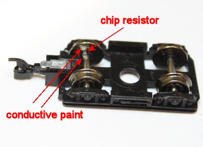
For obvious reasons, a resistor wheelset requires metal wheels. The Graham Farish wheels are metal, with one wheel pressed onto the axle and the other having a plastic insulating bush around the axle. the resistor is added to the axle with the bush, with one end on the axle and mounted flat on the inside of the wheel. where models have has plastic wheels, I've simply replaced then with Graham Farish spares which are readily available from BR Lines.
| Wheel | Part Number |
| 3 hole disc wagon | 379-410 |
| spoked wagon | 379-411 |
| solid coach | 379-412 |
To assemble a resistor wheelset, I have used the following process. It is best to do a batch of 10-20 axles at a time!
- Remove the axle from the model.
- Use a "back to back" gauge to get the wheel spacing along the axle correct. This is essential for good running.
- Use a modelling knife to "scratch" the back of the wheel and the axle where the resistor is to go.
- Use epoxy to attach the resistor. Use the tip of a knife to put a tiny dab on the wheel where the resistor will go, then use tweezers to position the resistor onto the wheel with one end touching the axle. Beware not to use too much adhesive: you are after an amount that when pressed out behind the resistor will still be smaller than the resistor. the tiniest dab is sufficient. you do NOT want it to squidge out at the ends.
- Let the epoxy set. (I use "slow set" epoxy so I can do a useful batch size; so 24 hours is good).
- You can do a check at this point: use a multimeter with tiny needle probes to check that the metallised ends of the resistor haven't been coated by epoxy. If you can measure 10KΩ the ends are accessible.
- Use a modelling knife to put a tiny dab of paint at each end of the resistor. This attaches one end to the axle, and the other to the wheel. The amount of paint is again tiny: it must not run along the whole resistor, otherwise it will short out the axle.
- When the paint is dry (possibly a few hours) use a multimeter to check the resistance across the axle. If you can measure 10KΩ it is fine; if you get infinite resistance, the paint has not connected one or both ends; if you get 0Ω (or close to it) then the paint has covered the whole resistor.
- (Some Graham Farish wheels have a plastic insulating section at each side - e.g. spoked and three hole wheels. Simply add more conductive paint on the other side from the axle to the metal rim, remembering to scuff the rim first to get a good contact).
There are several sorts of conductive paint, available from lots of suppliers. Both silver loaded and nickel loaded are available: the latter works fine and it is half the price. Shake it well before use. Mine is in the form of a "pen" from Maplin. I simply use the pen to deposit a blob onto a plastic surface, from which I pick up paint with the tip of a scalpel.