The track is wired in a way that is almost certainly over-engineered. It has been done this way for reliability, and for ease of maintenance. This is for the long haul: I don't want to be fixing it before it is finished!
Each piece of track has a pair of dropper wires: I am notrelying on electrical connection via the fishplates. This is almost certainly over-engineered. The dropper wires are 50-75mm lengths of 22SWG tinned copper wire, soldered to the rail bottoms before mounting. I have used 60%:40% leaded solder: lead-free solder melts at a much higher temperature and did NOT flow well at all. It may be possible to improve the "flow" that with different fluxes, but the temperature means more heat into the track and more opportunity to distort the plastic.
My CAD design shows the rail polarity, and location of power feeds to blocks. The rail polarity is marked by the rail being "red" or blue". The "red" rails are gapped between sections; the blue rail is continuous through the entire power zone. (The railway is also power zoned, and this makes wiring slightly more complex; the "blue" rail is also gapped between zones. See the power management section for more details).
|
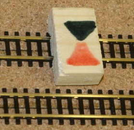
This "device" is simply a small piece of wood marked with the two track polarities - "red" and "black" corresponding to the CAD design. It makes it clear which dropper wire is which - they are then marked on the underside with a colour "spot". |
 |
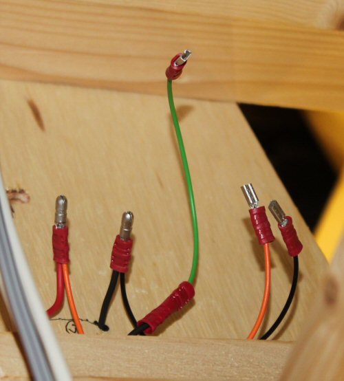
Once through the board, the dropper wires are fitted with coloured insulating sleeves, and terminated with a red male bullet crimp connector. These are readily available from many suppliers (buy in hundreds to keep the cost down). They terminate each dropper in a connector; everything is pushfit connectorised from there, and with no soldering needed under the railway. I used red and black sleeving, simply because I could get black at much lower cost than blue... I don't know why that is! Don't mess around with the crude crimp tools that act like a pair of pliers - it will take all day and be less reliable. Buy a ratchet action crimp tool and don't ever have to worry about joint reliability.
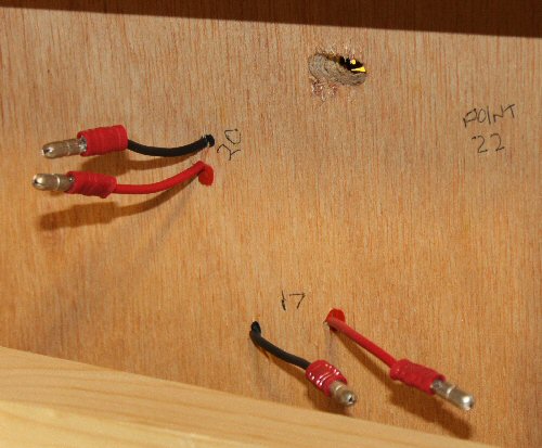
At this stage, each piece of track is connected via colour coded, insulated droppers to a pair of insulated terminals. Use a multimeter to make absolutely sure that the connections are right before proceeding. There should be no shorts between rails, and good connection to each dropper. As an observation, if this stage is completed as track is laid, it can be tested with trains running without fear of the droppers shorting below the baseboard.
The process for points is very similar. Each point has three dropper wires before it is lead (both rails, and frog). The point motors all switch the power to the frogs, and I've used a 2.8x0.8mm "tab" connector for those. The dropper wires need short flexible wires added to go to the point motor. the two outer rails simple have a flexible wire AND the dropper wire crimped into a bullet connector; the frog is joined to its flexible wire using a "butt splice2 crimp connector.