Points are all electrofrog, with frogs powered by a switch in the point motor. The centre two rails from the frog need to be isolated with nylon fishplates.
All points are operated remotely using point motors driven by DCC accessory decoders. Initially, SEEP PM-1 point motors have been used. These are solenoid motors with an integral switch for frog polarity.
The N gauge point tie bar doesn't move far. With the point motor mounted directly behind the 13mm thick baseboard, the point motor switch didn't move far enough for the switch to operate reliably: although its operating rod has some "sprint" to it, it just wasn't bending over a long enough length. The solution I've adopted is to mount the PM-1 motors on 10mm timber battens elow the baseboard to space them away from the track - now approx 23mm behind the base of the point. The spring rod then bends, allowing the solenoid armature & switch to move over its full length. The battens are pre-drilled with a 13mm hole, then glued underneath before the point motors are mounted.
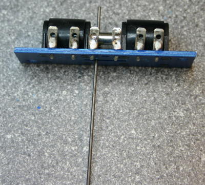
Wiring to the SEEP motors has caused major grief. Initially I used 2.8x0.8mm push fit "tab" connectors, with a tab soldered onto the motor. Unfortunately, the force needed tp push the spade connector onto it breaks the PCB track. The next approach has been to drill the PCI with a 1mm hole; the tab connector is then an interference fit into the hole. It can be solvered and the excess cut off. HOWEVER it is bad if there is any excess at all on the "baseboard" side of the PCB. The final approach is solder flying leads to the point motors, and to used crimp "bullet" connectors.
I have also had issues with the PCB switch not operating reliably (sometimes not making contact). A drop of switch cleaner has resolved that problem when it has occurred; it isn't clear whether that is a one-off fix or whether it is an enduring problem.